That bright blue arc, the rhythmic sizzle, and the molten metal flowing like liquid sunshine – if you’ve seen MIG welding in action, you’ve witnessed one of the most efficient metal-joining processes ever invented. But how does a MIG welder work when you pull that trigger? Understanding this technology transforms you from a button-pusher into a precision craftsman who controls metal at its most fundamental level. Whether you’re repairing a trailer hitch, building a custom bike frame, or just curious about the sparks flying in your garage, knowing the inner mechanics prevents costly mistakes and unlocks professional-quality results. In this guide, you’ll discover exactly how electricity, gas, and wire converge to fuse metal – plus critical adjustments that separate weak, porous welds from strong, clean joints.
Why Your MIG Welder Creates a Continuous Electrical Circuit for Welding
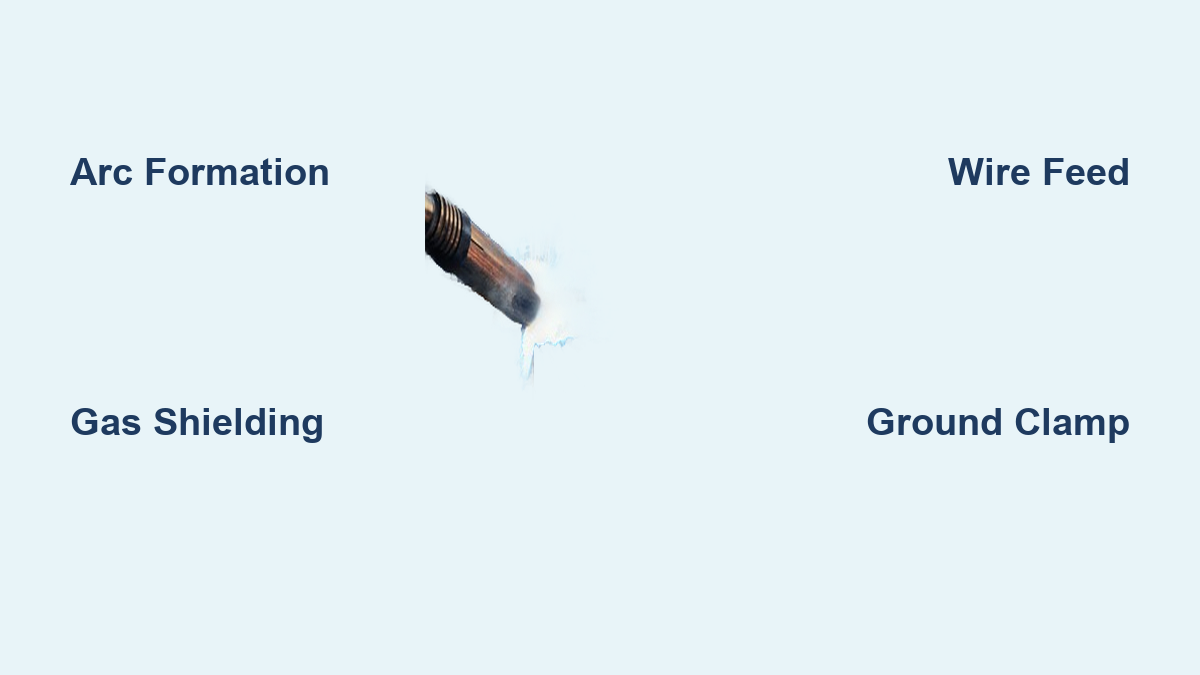
The moment you pull the trigger, your MIG welder completes a high-voltage electrical circuit that’s the heartbeat of the entire process. Unlike stick welding where the rod touches the workpiece, MIG uses a constantly feeding wire electrode that never contacts the metal. When you pull the trigger, the wire feeder pushes the consumable wire through the gun liner toward your workpiece. Just before contact, the power supply generates 15-40 volts that ionizes the gap, creating a sustained electric arc hotter than the sun’s surface (around 10,000°F). This arc melts both the wire electrode and the base metal, forming a molten weld pool. Crucially, the circuit only flows when the wire is actively feeding – stop the wire, and the arc extinguishes instantly. This “hot wire” system allows precise control impossible with manual rod welding.
What Happens When Voltage and Wire Speed Are Mismatched
- Too high voltage with slow wire speed: Causes excessive spatter and wide, shallow weld beads
- Low voltage with fast wire speed: Creates a stubbing effect where wire jams into the weld pool
- Perfect balance: Produces that signature “bacon sizzle” sound with minimal spatter
The Critical Shielding Gas Flow That Prevents Weld Contamination

While the arc does the melting, your MIG welder’s shielding gas system is the unsung hero protecting your weld from catastrophic failure. As soon as you pull the trigger, argon, CO2, or a gas blend floods the welding zone through the gun’s copper nozzle. This invisible gas curtain performs two vital functions: it displaces oxygen and nitrogen from the air that would otherwise cause porosity (tiny holes), and it stabilizes the electrical arc. For steel welding, 75% argon/25% CO2 is the gold standard – the CO2 boosts penetration while argon ensures smooth metal transfer. Aluminum requires pure argon to prevent oxidation. Without this gas shield, your weld would absorb atmospheric gases like a sponge, creating weak, brittle joints that fail under stress. Always check for gas flow before welding – a simple tissue test held near the nozzle should show steady movement.
How Gas Flow Rate Affects Different Metals
| Metal Type | Recommended PSI | Critical Warning Signs |
|---|---|---|
| Mild Steel | 20-25 PSI | Orange sparks = insufficient gas |
| Stainless Steel | 25-30 PSI | Black soot on weld = oxygen contamination |
| Aluminum | 25-35 PSI | Frothy weld pool = moisture in gas line |
How the Wire Feed System Powers Your Welding Precision
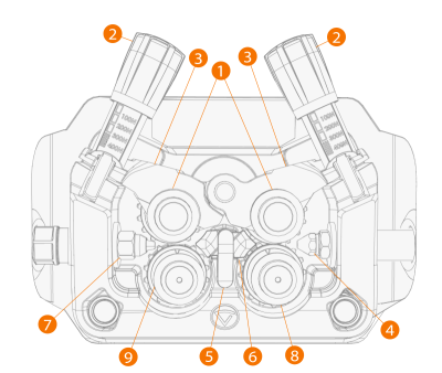
Your MIG welder’s wire feeder isn’t just a motor pushing spool – it’s a precision instrument controlling weld quality. Inside the machine, drive rolls grip the wire (typically .023″, .030″, or .035″ diameter) and feed it through a flexible conduit to the gun. The magic happens in the synergic control: when you adjust the voltage knob, the machine automatically calculates the optimal wire speed. Higher voltage requires faster wire feed to maintain arc stability. For thin 18-gauge steel, you might use 150 inches-per-minute wire speed at 17 volts; for 1/4″ plate, that jumps to 350 IPM at 24 volts. The contact tip inside the gun – often overlooked – must match your wire diameter exactly. A .035″ tip for .030″ wire causes erratic feeding and burnbacks where the wire fuses to the tip.
Three Deadly Wire Feed Mistakes to Avoid
- Over-tightened drive rolls: Flattens the wire causing inconsistent feeding
- Kinked liner: Creates “birdnesting” where wire jams mid-weld
- Worn contact tips: Causes arcing inside the gun that melts components
Step-by-Step: What Happens in 0.5 Seconds From Trigger Pull to Molten Metal
The entire MIG welding cycle operates at lightning speed – here’s exactly what occurs the moment you pull the trigger:
- 0.05 seconds: Gas solenoid opens, flooding nozzle with shielding gas
- 0.1 seconds: Wire feeder engages, pushing wire toward workpiece
- 0.15 seconds: Wire contacts metal, creating a short circuit
- 0.2 seconds: Power supply detects short and increases current
- 0.25 seconds: Arc ionizes, wire melts at contact point
- 0.3 seconds: Metal droplets transfer across arc via one of three modes:
– Short-circuiting: For thin metals (<1/8″), droplets “short” to workpiece
– Globular: Less common, large unstable drops (mostly with CO2)
– Spray transfer: High-speed fine droplets for thick materials - 0.5 seconds: Molten pool forms as base metal melts
This entire sequence repeats 100+ times per second during welding. Any disruption – like inconsistent gas flow or voltage drop – interrupts this delicate balance.
Why Your MIG Welder Settings Differ for Steel vs. Aluminum
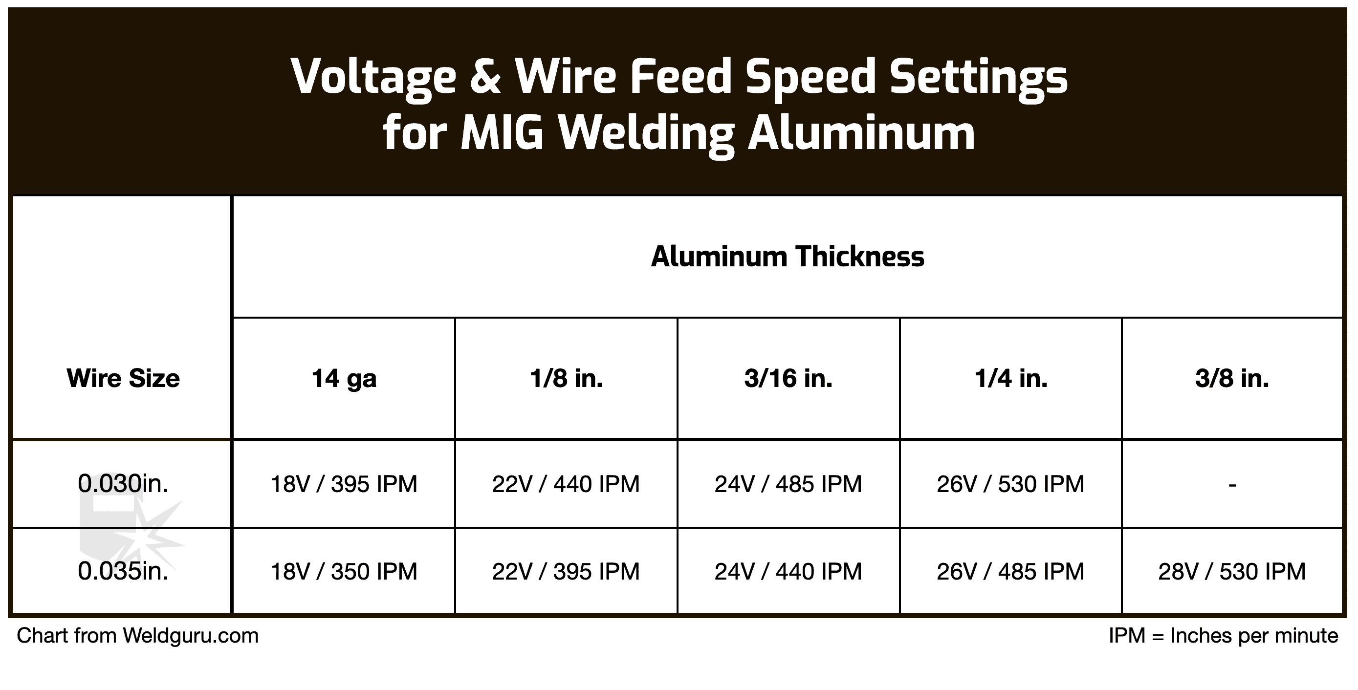
Aluminum demands completely different handling than steel due to its thermal properties. While steel welds at 17-25 volts, aluminum requires 22-30 volts because it conducts heat 5x faster. More critically, aluminum wire is soft and prone to “nesting” in the feed system. You must use:
– A spool gun or push-pull system (never standard liners)
– Pure argon shielding gas (no CO2)
– Reverse-polarity DCEN (electrode negative)
– Higher wire speeds (250-500 IPM vs 150-350 for steel)
The real danger? Aluminum’s oxide layer melts at 3,700°F while the base metal melts at 1,200°F. If your voltage is too low, you’ll weld on top of the oxide instead of through it, causing trapped contaminants. Always use a stainless steel brush dedicated to aluminum to clean before welding.
Troubleshooting Weak Arcs: The Ground Clamp Connection You’re Ignoring
Over 60% of “weak arc” complaints trace back to a single overlooked component: the ground clamp. Your MIG welder’s circuit must flow through the workpiece back to the machine. If the clamp grips rusty metal or has loose connections, resistance builds up, starving your arc of power. Always:
– Clean the clamp contact point to bare metal
– Position the clamp within 2 feet of the weld zone
– Never attach to painted or oily surfaces
– Check for cracked cable insulation
When troubleshooting, perform the “bright light test”: weld with the hood up (briefly!) in a dark room. A healthy arc glows bright white-blue. A dim orange arc indicates voltage drop from poor grounding.
Safety Essentials That Prevent MIG Welding Disasters
That brilliant arc emits UV radiation 10x stronger than midday sun – enough to give severe “welder’s flash” in seconds. Beyond standard leather gloves and a #10 helmet shade, critical protections include:
– Fire prevention: Keep a 10-foot radius clear of combustibles; use welding blankets
– Gas hazards: Store cylinders vertically chained; never use oil near regulators
– Electrical safety: Wear dry gloves; inspect cables for damage weekly
– Fume control: Always weld upwind or use extraction systems (manganese fumes cause neurological damage)
Never skip the “5-minute rule”: after welding stops, wait 5 minutes before handling workpieces. Residual heat can cause severe burns even when metal looks cool.
How to Maintain Your MIG Welder for Flawless Performance
Preventative maintenance takes 10 minutes but saves hours of troubleshooting. After every 40 hours of use:
1. Replace contact tips (they wear microscopic holes)
2. Clean drive rolls with wire brush
3. Blow out gun liner with compressed air
4. Check gas hose for cracks
5. Tighten all electrical connections
For aluminum welding, replace the gun liner before it shows wear – aluminum shavings embed in liners causing feed issues. Keep a log of consumable changes; sudden performance drops often trace to overlooked wear items.
Final Note: Mastering how a MIG welder works transforms confusing sparks into controlled metal fusion. Remember the critical triad: consistent wire feed, proper shielding gas coverage, and correct voltage/wire speed balance. When your welds develop that smooth “stacked dime” appearance with minimal spatter, you’ve achieved the perfect arc equilibrium. Start with clean metal, verify your ground connection, and make micro-adjustments to voltage – these small steps prevent 90% of common welding defects. Now that you understand the science behind the sizzle, every trigger pull becomes a precise metalworking operation rather than a guessing game. Ready to test your knowledge? Try welding a lap joint on scrap metal while focusing solely on maintaining that ideal 1/4-inch arc length – the visual feedback will confirm your understanding of the MIG welding process.
Leave a Reply