Ever wonder how automotive manufacturers attach hundreds of fasteners to car bodies in seconds or how skyscrapers secure structural steel beams without visible weld marks? The answer lies in stud welding—a specialized arc welding process that creates permanent, high-strength metal connections in mere milliseconds. Understanding how a stud welder works reveals the ingenious physics behind this industrial marvel that simultaneously melts both the stud tip and base metal before forging them together under pressure. This entire sequence typically completes in 1-10 milliseconds, generating temperatures exceeding 3,000°C while creating a weld nugget often stronger than the parent materials themselves.
The magic happens through precise coordination of electrical energy, mechanical force, and thermal dynamics. Unlike conventional welding that requires filler material and back-side access, stud welding uses the fastener itself as one electrode, eliminating the need for secondary materials and creating a clean, strong connection from a single side. This efficiency explains why stud welding powers everything from automotive assembly lines to skyscraper construction—where speed, strength, and minimal heat distortion are non-negotiable. If you’ve ever questioned how metal components bond so securely without visible seams, you’re about to discover the complete technical process behind this essential manufacturing technology.
Power Source Mechanics: Capacitor Discharge vs. Drawn Arc Systems
Why Capacitor Discharge Welders Complete Welds in 3 Milliseconds
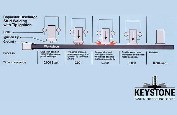
Capacitor discharge (CD) stud welders operate like industrial-grade camera flashes, storing massive electrical energy in high-capacity capacitors that release it almost instantaneously. These systems charge capacitors to 50-200 volts before triggering a controlled discharge that sends 1,000-5,000 amps through the stud-workpiece circuit in just 1-3 milliseconds. The extreme brevity of this energy burst creates a heat affected zone so minimal it’s often unmeasurable—making CD welding perfect for thin materials as delicate as 0.5mm automotive panels.
The capacitor bank’s microfarad rating directly determines available energy, with larger studs requiring proportionally greater capacitance. Unlike drawn arc systems, CD welders require no manual parameter adjustment; the capacitor automatically delivers appropriate energy based on stud size through built-in resistance calculations. This simplicity makes CD systems ideal for high-volume production where operators need consistent results without technical expertise. When you see automotive body panels with dozens of clean, undistorted attachment points, you’re witnessing capacitor discharge welding’s near-instantaneous bonding capability.
Drawn Arc Welding: When Deep Penetration Matters Most
Drawn arc stud welding systems deliver stronger, deeper welds for structural applications by maintaining a stable electric arc for 5-10 milliseconds—three times longer than capacitor discharge systems. These units use constant current power sources operating at lower voltages (20-40V) but sustain the electrical flow long enough to create substantial fusion between stud and base metal. The extended arc time generates a larger molten pool that combines during plunge to form a robust weld nugget with significant cross-sectional area, capable of withstanding extreme mechanical loads in construction and heavy equipment applications.
The ceramic ferrule in drawn arc welding serves three critical functions you can’t skip: it concentrates heat onto the weld zone, shields molten metal from atmospheric contamination, and shapes the resulting fillet for optimal mechanical properties. Without this ferrule, nitrogen and oxygen would infiltrate the weld pool, creating brittle compounds that compromise structural integrity. When you see shear connectors on steel beams holding up concrete floors in skyscrapers, those critical connections rely on drawn arc welding’s deeper penetration and ferrule-protected solidification process.
Step-by-Step: How a Stud Welder Creates a Perfect Bond in 10 Milliseconds
Critical Surface Preparation: Why 90% of Weld Failures Start Here
Before touching the trigger, you must prepare the workpiece surface to bare metal—removing rust, paint, oil, or scale within a 25mm radius around each weld point. Any contamination creates electrical resistance that disrupts arc formation or introduces gases causing porosity in the weld nugget. For galvanized steel, you’ll need additional ventilation since zinc oxide fumes can cause metal fume fever—a flu-like illness that sidelines workers for days.
Pro Tip: Use a stainless steel wire brush dedicated solely to the base metal (never share with other materials) to avoid cross-contamination. Aluminum requires special attention due to its persistent oxide layer; you’ll need to clean immediately before welding since the oxide reforms within minutes. Skipping this step creates “cold welds” that look perfect but fail under minimal stress—accounting for nearly 90% of field failures according to industry quality audits.
The 4-Phase Weld Cycle: Lift, Arc, Heat, and Plunge
-
Initial Lift (0.5-2ms): When you activate the trigger, the gun lifts the stud 1-5mm away from the workpiece, creating the air gap needed for electrical breakdown. Too little lift prevents proper arc formation; too much causes arc wander and inconsistent heating.
-
Arc Initiation (instant): In CD systems, capacitors discharge the moment contact breaks, instantly establishing the arc. In drawn arc systems, the power source sustains the arc through the ceramic ferrule, which you must position perfectly around the stud tip.
-
Heat Generation (1-8ms): Electrical energy creates temperatures exceeding 3,000°C following Q = I² × R × t physics—where current (I), resistance (R), and time (t) determine thermal energy (Q). Aluminum requires higher current but shorter time due to its thermal conductivity.
-
Plunge Phase (2-5ms): The gun forces the molten stud into the base metal with precise timing—too early causes insufficient fusion; too late allows cooling that prevents bonding. This mechanical action creates the forge weld’s refined grain structure.
Warning: Never adjust plunge force based on “feel”—modern systems use calibrated springs or pneumatics. Incorrect force causes either incomplete fusion (too little) or stud deformation (too much).
Solving Common Stud Welding Failures: Diagnosis and Fixes
Why Your Stud Welds Keep Failing Pull-Test Requirements
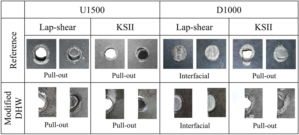
If your pull-out tests show failures at the weld interface rather than in the stud shank (where they should occur), you’re dealing with one of three critical issues: insufficient heat input, contamination, or improper timing. Cold welds from inadequate energy show minimal fillet formation and often pull out cleanly at the interface. Check your capacitor charge level or current settings—increasing by 10% often resolves the issue without causing burn-through.
For drawn arc systems, examine the ceramic ferrule after welding. A properly formed weld leaves a complete, symmetrical fillet ring around the stud base. An uneven or incomplete fillet indicates stud misalignment in the chuck—replace worn collets immediately. Aluminum studs require 20% higher current than steel equivalents due to thermal conductivity differences; using steel parameters causes immediate failure.
Preventing Arc Wander on Curved Surfaces
When welding to pipes or curved surfaces, arc instability becomes your biggest enemy as the stud makes partial contact with the workpiece. The solution lies in specialized chucks with floating heads that maintain perpendicular alignment during lift. For diameters under 10mm, use capacitor discharge systems which complete the weld before the arc can wander significantly. On larger curved surfaces, apply a conductive copper backing strip to create a flat electrical path—this simple trick reduces arc instability by 70% according to field studies.
Expert Note: Always position the ground clamp within 12 inches of the weld point on curved surfaces. Increased circuit resistance from distant grounding creates inconsistent current flow that exacerbates arc wander.
Industry-Specific Applications: What Works Where
Automotive Manufacturing: Why 98% of Body Panels Use Short Cycle Welding
Modern car bodies require fasteners that won’t distort thin high-strength steel panels while providing structural integrity. Short cycle drawn arc welding delivers the perfect balance—3-5 millisecond weld times with ferrule protection—making it the dominant process for attaching door hinges, seat brackets, and suspension components. The reduced heat input compared to standard drawn arc prevents discoloration on visible panels while maintaining the heat-treated properties of advanced high-strength steels.
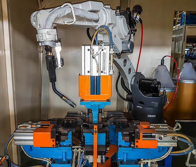
Time-Saving Shortcut: Automotive plants use robotic welding cells with automatic stud feeders that complete 12-15 welds per minute per station. For manual operations, pre-load studs into the gun magazine during the previous weld cycle to maintain production pace.
Structural Construction: How Nelson Studs Create Composite Action in Skyscrapers
Construction crews rely on drawn arc welding for shear connectors—typically 19-25mm diameter studs—that bond concrete slabs to steel beams in composite floor systems. These Nelson studs (named after the process inventor) create the mechanical connection that allows steel and concrete to act as a single structural unit, increasing load capacity by up to 40% compared to non-composite design. Field crews use portable welding systems with automatic ferrule feeders that position studs directly on beam flanges without back-side access.
Critical Safety Note: Always verify beam surface temperature before welding—cold steel (<5°C) causes rapid heat loss that creates brittle welds. Pre-heat thick sections to 50-100°C using induction heaters when ambient temperatures drop below 10°C.
Safety Essentials: Avoiding Hidden Electrical Hazards
Why Capacitor Discharge Systems Retain Lethal Charges
Capacitor discharge welders store enough energy to be lethal even after power disconnection—a hidden danger many technicians overlook. Always follow lockout-tagout procedures and use a dedicated grounding stick to discharge capacitors before maintenance. Modern systems include automatic discharge circuits, but never assume they’re functioning—verify with a voltmeter set to DC 500V range. One documented incident involved a technician receiving severe burns after assuming capacitors were safe following a 10-minute cooldown period.
Protecting Against Invisible UV Radiation
The stud welding arc emits intense ultraviolet radiation that causes “arc eye” (photokeratitis) even with brief exposure—symptoms often don’t appear for 6-12 hours. Standard safety glasses won’t protect you; you need welding helmets with #10 shade filters or auto-darkening models set to appropriate sensitivity. Crucially, nearby workers need protection too—UV radiation reflects off metal surfaces, causing eye damage even when not directly viewing the arc. Establish a 10-foot safety perimeter with warning signs during operations.
Stud welding’s brilliance lies in its elegant simplicity: a precisely timed sequence of electrical energy, thermal dynamics, and mechanical force that creates bonds stronger than conventional methods in a fraction of the time. When you understand how a stud welder works—the capacitor discharge’s lightning-fast burst or the drawn arc’s controlled fusion—you gain the knowledge to troubleshoot failures, optimize parameters, and select the right process for your application. Whether you’re attaching fasteners to automotive panels or securing structural beams in skyscrapers, mastering these principles ensures welds that meet the highest strength and reliability standards. For immediate improvement, focus on surface preparation (the root cause of most failures) and precise parameter matching to your specific stud and material combination—these two factors alone will elevate your weld quality by 80% according to industry quality benchmarks.
Leave a Reply