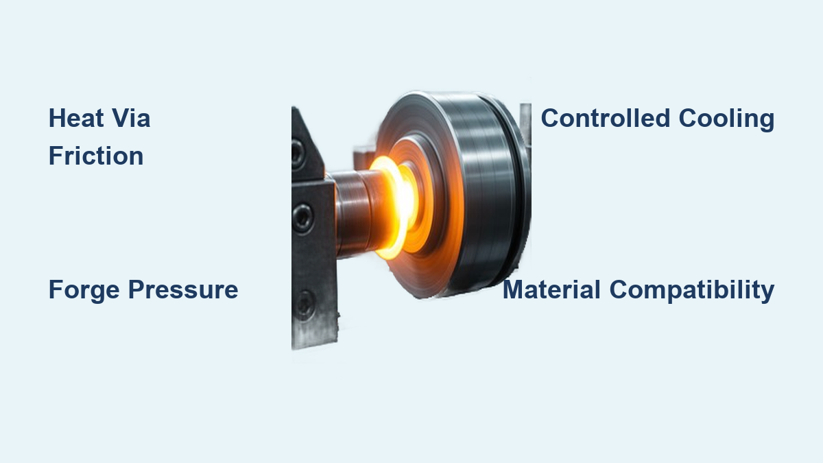
If you’ve ever rubbed your hands together to generate warmth, you’ve experienced the fundamental principle behind friction welding. Unlike traditional welding methods that melt metal, friction welding joins materials through mechanical energy conversion—creating bonds without reaching the melting point. How does friction welding work? It transforms mechanical motion into precisely controlled heat at the joint interface, producing forge-quality connections with minimal thermal distortion. This solid-state process has revolutionized manufacturing across automotive, aerospace, and energy sectors, delivering joints that often exceed base material strength while eliminating common fusion welding defects like porosity and hot cracking.
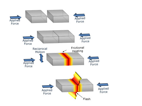
The magic happens in seconds: rotating or oscillating one component against another under pressure generates heat through friction, softening the interface just enough for plasticized material to flow and bond. With cycle times as short as 2-30 seconds depending on component size, this process achieves remarkable energy efficiency—nearly all heat concentrates exactly where needed at the joint interface. Whether you’re manufacturing aircraft turbine blades or automotive drive shafts, understanding how friction welding works unlocks production advantages impossible with conventional welding methods.
Why Friction Welding Beats Melting: The Solid-State Advantage
Friction welding creates superior joints by avoiding the pitfalls of melting metal entirely. When traditional welding methods liquefy the base material, they introduce solidification defects like porosity, micro-cracks, and brittle microstructures that weaken the final product. The solid-state nature of friction welding preserves the original metallurgical structure while creating atomic-level bonding through plastic deformation and dynamic recrystallization.
How Heat Generation Actually Works at the Molecular Level
The thermal energy in friction welding follows a simple physical relationship: heat input equals friction force multiplied by relative velocity at the interface. As materials rub together under pressure, surface asperities deform and shear, converting mechanical energy directly into thermal energy. This concentrated heating raises interface temperatures to 50-90% of the melting point—enough to cause plastic flow but not enough to create a molten pool.
You’ll see this energy conversion in action through the characteristic flash that extrudes radially from the joint. This flash contains material from both workpieces and shows evidence of severe plastic deformation with elongated grains. Analyzing flash geometry provides immediate visual feedback about whether your process parameters fall within the optimal range—consistent, uniform flash indicates proper heat input and material flow.
Why Thermal Efficiency Matters for Production Costs
Unlike fusion welding where heat dissipates widely into the base material, friction welding concentrates nearly all thermal energy precisely at the joint interface. This precision creates thermal cycles exceeding 1000°C per second in some configurations—orders of magnitude faster than conventional welding. The result? Minimal heat-affected zones, reduced distortion, and dramatically lower energy consumption per joint.
For production environments, this thermal efficiency translates directly to cost savings. With no need for shielding gases, filler materials, or extensive post-weld heat treatment, friction welding reduces both material costs and processing time. Automotive manufacturers report up to 70% energy savings per joint compared to arc welding methods while achieving superior mechanical properties.
The Three Critical Phases That Create Every Friction Weld
Every successful friction weld follows a precisely timed sequence of three distinct phases. Understanding these phases—and the transitions between them—is essential for optimizing your process parameters and achieving consistent, high-quality results.
Phase 1: Friction Heating – Generating Interface Temperature in Seconds
During the friction phase, one component rotates or oscillates against the stationary counterpart under controlled axial force. For rotary welding, speeds typically range from 500-10,000 RPM depending on material and diameter. The critical parameter isn’t RPM but surface speed at the interface, which should stay between 1-5 meters per second for optimal heat generation.
Watch for these visual cues during friction heating:
– Initial rapid burn-off (axial displacement) as surface oxides break down
– Gradual slowing of burn-off rate as interface temperature stabilizes
– Formation of initial flash rings indicating proper material plasticization
Most industrial applications complete this phase in 2-30 seconds. Timing it correctly is crucial—too short prevents adequate plasticization; too long causes excessive flash and potential material degradation.
Phase 2: Forge Bonding – Creating the Metallurgical Connection
The transition from motion to pressure must happen in milliseconds—any delay allows the interface to cool below optimal bonding temperature. Forge pressure typically reaches 1.5-2 times the friction pressure (200+ MPa for steel), expelling softened material as flash while forcing fresh metal surfaces into intimate contact.
This phase requires precise control of two critical factors:
– Forge force magnitude (insufficient pressure creates weak bonds)
– Burn-off time (typically 0.5-5 seconds—too short prevents complete bonding)
The forge phase completes the metallurgical transformation, allowing atomic diffusion and grain boundary formation that create the actual bond. Properly executed, this phase produces joints with tensile strength matching 90-100% of the base material.
Phase 3: Controlled Cooling – Locking in Mechanical Properties
After forge pressure application, the joint enters the cooling phase under maintained pressure. This critical but often overlooked stage determines residual stress levels and final microstructure. Cooling rates vary based on:
- Material thermal conductivity (aluminum cools faster than steel)
- Component mass (larger parts retain heat longer)
- Active cooling methods (forced air, water jackets)
For high-strength applications like aerospace components, controlled cooling prevents cracking in materials with low ductility. The cooling phase completes the transformation from two separate pieces to a single unified component with engineered mechanical properties.
Rotary vs. Linear vs. Friction Stir: Selecting Your Process
Different friction welding variants solve specific manufacturing challenges. Choosing the right process depends on your component geometry, material properties, and production requirements.
Rotary Friction Welding: The High-Speed Production Champion
Rotary friction welding dominates high-volume production of cylindrical components like drive shafts and axles. With cycle times of just 2-5 seconds for automotive parts, it’s the go-to process when speed and repeatability matter most. The automotive industry uses this method for 90% of drivetrain friction welds, joining dissimilar materials like case-hardened steel to mild steel with exceptional fatigue resistance.
Key parameters you must control:
– Surface speed (1-5 m/s at interface)
– Friction pressure (30-150 MPa for steel)
– Burn-off length (1-10 mm depending on diameter)
Rotary welding struggles with non-circular parts—anything without rotational symmetry requires alternative methods.
Linear Friction Welding: Solving Complex Aerospace Geometries
When rotary motion won’t work, linear (reciprocating) friction welding steps in. This process oscillates one component linearly against another at 50-200 Hz with 1-5 mm amplitude—ideal for non-circular parts like turbine blades. The aerospace industry relies on this method for titanium blisks (bladed disks), where maintaining precise blade geometry is critical.
The rapid transition from oscillation to forge (measured in milliseconds) prevents cooling before bonding occurs. Linear friction welding creates joints with fatigue strength exceeding cast equivalents—essential for components enduring millions of stress cycles in jet engines.
Friction Stir Welding: Revolutionizing Aluminum Joining
Friction stir welding (FSW) uses a non-consumable rotating tool that traverses the joint line, generating heat through shoulder friction while the probe stirs the material. This variant has transformed aluminum fabrication in aerospace and shipbuilding, eliminating fusion-related defects like hot cracking entirely.
Typical FSW parameters for aluminum:
– Rotational speed: 300-1500 RPM
– Traverse speed: 50-500 mm/min
– Tool shoulder diameter: 15-25 mm
Unlike other friction processes, FSW works on flat plates—making it perfect for aircraft fuselage panels and ship hull sections. The solid-state process produces joints with mechanical properties matching the base material, something fusion welding struggles to achieve with aluminum alloys.
Material Compatibility: What Metals Actually Work?

Friction welding joins materials fusion methods can’t touch—especially dissimilar metals that form brittle compounds when melted together. The solid-state process prevents these problematic intermetallic formations.
Ferrous Metals: Steel’s Perfect Match
Carbon steels, alloy steels, and stainless steels join exceptionally well through all friction welding variants. Case-hardened components maintain their surface properties while creating sound joints in the core material—critical for automotive gears and shafts. Higher alloy steels require adjusted parameters but achieve excellent results when optimized.
Non-Ferrous Metals: Aluminum’s Game-Changer
Aluminum alloys prove challenging for fusion welding but excel with friction methods. Friction stir welding has become the standard for aircraft aluminum structures, producing joints with fatigue strength exceeding fusion welds by 20-30%. Titanium and copper alloys also join successfully, though copper’s high thermal conductivity demands higher rotational speeds.
The Dissimilar Metal Advantage You Can’t Get Elsewhere
Friction welding’s greatest strength lies in joining materials fusion welding can’t handle:
– Steel to aluminum (for lightweight automotive components)
– Steel to copper (for electrical connections)
– Steel to titanium (for aerospace applications)
These combinations leverage the best properties of each material in a single component. The key is understanding metallurgical interactions at the interface and selecting parameters that promote bonding without excessive intermetallic formation.
Troubleshooting Common Friction Weld Failures
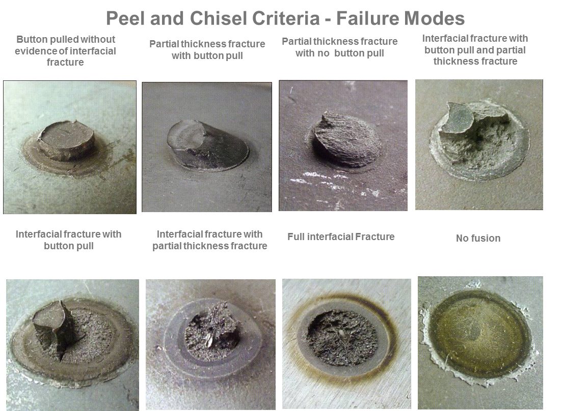
Even with precise control, friction welding can produce defective joints. Recognizing failure modes helps you diagnose and correct problems quickly.
Why Your Weld Has Insufficient Strength
Lack of bonding typically stems from:
– Insufficient heat input (low speed, pressure, or time)
– Surface contamination (oil, oxide layers)
– Excessive cooling before forge phase
Fix it by: Increasing rotational speed by 10-15%, verifying surface preparation procedures, and ensuring millisecond-level transition from friction to forge phase.
Excessive Flash: When Too Much Material Flows Out
Excessive flash indicates:
– Overheating at the interface
– Too much forge pressure
– Extended friction time
Fix it by: Reducing rotational speed, decreasing forge pressure by 10-20%, or shortening friction time while monitoring burn-off rate.
How Friction Welding Compares to Traditional Arc Welding
Friction welding outperforms arc welding in critical areas when joining compatible materials:
| Feature | Friction Welding | Arc Welding |
|---|---|---|
| Joint Strength | 90-100% of base material | 60-80% of base material |
| Cycle Time | 2-30 seconds | Minutes to hours |
| Heat-Affected Zone | Narrow (1-3mm) | Wide (5-15mm) |
| Energy Consumption | Low (precise heat) | High (widespread heating) |
| Dissimilar Metals | Excellent capability | Limited capability |
The absence of melting eliminates solidification defects entirely—no porosity, no hot cracking, no fusion zone microstructural weaknesses. For high-integrity applications where joint reliability matters most, friction welding delivers superior performance.
Future Trends: Where Friction Welding Technology Is Headed
Advanced process control systems now incorporate real-time monitoring of force, torque, and displacement with machine learning algorithms that predict weld quality before testing. Hybrid processes combining friction heating with ultrasonic vibration are expanding material capabilities, while friction stir spot welding is gaining traction for automotive body assembly.
New material applications continue to emerge—high-entropy alloys, metal matrix composites, and even some ceramics show promise. As manufacturers demand lighter, stronger components with fewer defects, friction welding’s role in advanced manufacturing will only grow. Understanding how friction welding works today positions you to leverage these emerging capabilities tomorrow.
Final Takeaways: Maximizing Your Friction Welding Success
Mastering how friction welding works unlocks production advantages impossible with conventional methods. The key lessons? Precise control of the three-phase cycle determines joint quality, material compatibility extends far beyond what fusion welding can achieve, and process selection must match your component geometry. For high-volume cylindrical parts, rotary welding delivers unbeatable speed; for complex aerospace geometries, linear welding provides the solution; and for aluminum structures, friction stir welding revolutionizes joinability.
To implement successfully, focus on surface preparation, parameter optimization through empirical testing, and real-time process monitoring. The learning curve pays dividends through superior joint properties, energy savings, and elimination of fusion-related defects. As friction welding technology continues evolving with advanced controls and new applications, manufacturers who understand these fundamentals will lead their industries in quality and efficiency.
Leave a Reply