Have you ever wondered how MIG welding creates those strong, smooth metal joints you see in automotive repairs and metal fabrication shops? How does MIG welding work through that combination of electricity, wire, and gas to fuse metals together with such precision? The process relies on a continuous electrical arc between a consumable wire electrode and the base metal, protected by shielding gas that prevents atmospheric contamination. This technical guide explains the complete MIG welding operation from power source to solidified weld bead, revealing why this method dominates modern fabrication across industries from automotive repair to aerospace manufacturing.
Unlike stick welding that requires frequent electrode changes, MIG welding’s continuous wire feed enables longer, more consistent welds with minimal interruption. The process combines electrical energy, consumable electrode wire, and protective gas in a precisely coordinated system that melts both the wire and base metal to form a metallurgical bond. Whether you’re troubleshooting weld defects, selecting equipment for your workshop, or simply seeking to understand the science behind the sparks, this detailed explanation covers everything you need to know about how MIG welding works.
Power Source Mechanics: How Electricity Creates the Welding Arc
Your MIG welder’s power source transforms standard electrical supply into the controlled current needed for stable arc formation. Most professional units accept 230-480 volts from industrial power sources, while hobbyist machines operate on standard 110-220 volt household current. The power source maintains consistent voltage and amperage output despite fluctuations in your electrical supply or changes in arc length—critical for producing uniform weld quality throughout your work.
Modern MIG power sources fall into two main categories with distinct advantages:
- Transformer-based units: Use traditional electrical transformers to step down voltage and increase amperage, offering proven reliability but significant weight and bulk
- Inverter-based units: Convert power more efficiently using high-frequency electronics, resulting in lighter, more compact machines with advanced features like synergic welding programs
The power source’s duty cycle determines how long you can weld at rated output before requiring cooling. Professional units typically offer 60-100% duty cycles at 200-500 amps, meaning they can weld continuously at maximum output. Hobbyist machines often provide 30-60% duty cycles at lower amperage ratings, requiring more frequent breaks during extended welding sessions. Choosing a power source with appropriate duty cycle directly impacts your ability to weld thicker materials consistently.
Voltage and Amperage Relationship Explained
The relationship between voltage and amperage in MIG welding differs significantly from other processes. Unlike stick welding where you set amperage directly, MIG welding primarily uses wire feed speed to control heat input. As you increase wire feed speed, the system automatically increases amperage to maintain the proper arc length. This synergic relationship simplifies parameter selection because:
- Higher wire feed speeds = more electrode material = higher amperage = greater heat input
- Lower wire feed speeds = less electrode material = lower amperage = reduced heat input
Pro Tip: When starting a new project, set your voltage first based on material thickness, then adjust wire feed speed until you achieve the desired penetration and bead profile. This method gives you more precise control than randomly adjusting both parameters simultaneously.
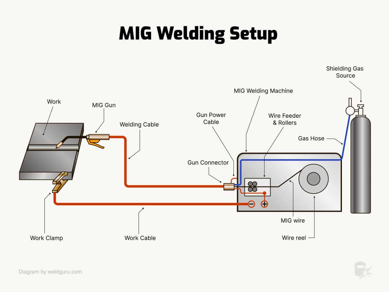
Wire Feed System: Continuous Electrode Delivery Explained

The wire feed mechanism delivers your consumable electrode to the weld pool through a precisely controlled system that distinguishes MIG welding from processes requiring frequent electrode changes. This continuous feed enables longer, more consistent welds with minimal interruption, dramatically improving productivity in fabrication environments. Your wire feed system consists of three critical components working in harmony:
- Wire spool: Holds the consumable electrode (typically 2-30 pounds for hobbyist use, 50+ pounds for production)
- Drive mechanism: Pushes wire through the torch using either four-roll, two-roll, or single-roll configurations
- Liner and guide tubes: Deliver wire from the drive mechanism to the welding torch with minimal resistance
Four-roll drive systems provide the most consistent feed pressure while minimizing wire deformation—essential when feeding soft aluminum wires or larger diameters without jamming. Two-roll systems offer adequate performance for general steel welding at lower cost, while single-roll designs suit light-duty applications where consistent feed accuracy is less critical.
Wire Feed Speed Settings: The Heart of MIG Control
Wire feed speed, measured in inches per minute (IPM), directly correlates with amperage output in most MIG applications. This relationship simplifies parameter selection because you primarily control heat input through wire feed speed adjustments rather than separately setting amperage. Typical wire feed speeds range from:
- 50-200 IPM for thin materials (22-16 gauge)
- 200-400 IPM for medium thickness (1/8-1/4 inch)
- 400-800 IPM for thick materials (1/4 inch and above)
Warning: Incorrect wire feed speed causes most common MIG welding problems. Too slow results in cold welds with poor penetration, while too fast causes excessive spatter and potential burn-through on thin materials. Always start with manufacturer recommendations for your specific wire diameter and material thickness.
Shielding Gas Protection: Why Contamination Prevention Matters
Shielding gas creates an invisible protective envelope around your weld pool, displacing atmospheric oxygen, nitrogen, and water vapor that would otherwise cause porosity, oxidation, and degraded mechanical properties. Without effective shielding, even the most carefully prepared joint produces weak, porous welds prone to failure. The gas flows through your welding torch nozzle, surrounding the wire extension and molten pool to prevent atmospheric contamination during the critical solidification phase.
Argon vs. CO2: Choosing the Right Gas for Your Metal
The shielding gas you select directly impacts weld quality, penetration profile, and arc characteristics. Understanding your options prevents costly mistakes and wasted materials:
- Pure argon: Best for non-ferrous metals like aluminum and copper, providing excellent cleaning action and minimal spatter. Avoid using pure argon on steel—it creates narrow, deeply penetrating beads prone to lack of fusion.
- Pure CO2: Offers deep penetration and high deposition rates at low cost but produces a turbulent arc with significant spatter. Suitable for heavy structural welding where appearance matters less than penetration depth.
- 75/25 argon-CO2 blend: The most common gas for steel welding, balancing deep penetration with stable arc characteristics. Produces minimal spatter and adequate penetration for most fabrication applications.
Expert Note: When welding stainless steel, use tri-gas blends incorporating 2-5% oxygen with argon and CO2. The oxygen acts as a surfactant, reducing surface tension for improved wetting action without compromising corrosion resistance.
Gas Flow Rate Optimization: Avoiding Porosity Issues
Proper gas flow rate ensures complete coverage without creating turbulence that draws in atmospheric contaminants. Typical flow rates range from:
- 15-20 CFH for indoor work on thin materials
- 20-30 CFH for standard steel fabrication
- 30-50 CFH for outdoor work, aluminum welding, or large nozzle applications
Check your gas flow meter before each welding session—flow rates outside the recommended range indicate problems requiring correction. If you notice porosity in your welds, systematically check:
– Gas cylinder pressure (should be above 200 PSI)
– Flow meter settings
– Hose connections for leaks
– Nozzle condition (spatter buildup restricts gas flow)
Metal Transfer Modes: How Molten Droplets Cross the Arc Gap
The manner in which molten metal moves from your electrode wire to the weld pool significantly impacts weld characteristics, suitable applications, and required parameters. MIG welding supports four distinct transfer modes, each with unique advantages and limitations that determine when and where you should employ each method.
Short Circuit Transfer: Low-Heat Welding for Thin Materials
Short circuit transfer occurs when your wire electrode repeatedly contacts the weld pool, creating a short circuit that burns back and restarts the arc. This cycle repeats 20-200 times per second, producing the characteristic buzzing sound of MIG welding and transferring small droplets across the minimal arc gap. The frequent contact events limit overall current flow, resulting in low heat input that makes this mode ideal for:
- Materials thinner than 1/8 inch
- All welding positions (flat, horizontal, vertical, and overhead)
- Situations requiring minimal distortion
Pro Tip: When using short circuit transfer, maintain a consistent wire extension of 3/8 to 5/8 inch. Too short causes contact tip melting, while too long leads to poor arc stability and lack of penetration.
Spray Transfer: High-Speed Production Welding Techniques
Spray transfer uses higher voltage and current levels to establish a stable, continuous stream of small molten droplets that transfer across the arc without shorting events. The arc column becomes clearly visible with a distinctive hissing sound, producing deep, narrow penetration with exceptionally high deposition rates. Spray transfer requires:
- Argon-rich shielding gas (at least 80% argon)
- Higher voltage settings than short circuit transfer
- Materials 1/8 inch and thicker
The high deposition rates of spray transfer make it highly efficient for flat-position welding where production speed takes priority over positional flexibility. However, the increased heat input limits its usefulness on thin materials and makes it impractical for vertical or overhead work where the large weld pool would sag.
Step-by-Step Process: From Arc Initiation to Solidification
Starting the Arc: Proper Technique for Clean Welds
Your MIG welding process begins when you momentarily touch the wire tip to the workpiece while wire feed remains active, creating the short circuit that initiates current flow and establishes the arc. This “scratch start” method requires minimal practice to master—think of it like striking a match with controlled pressure. If the wire sticks excessively or spatters wildly, your parameters need adjustment before proceeding.
Once established, maintain proper wire extension—the distance from contact tip to weld pool—typically 3/8 to 5/8 inch depending on wire diameter. This critical measurement directly impacts arc stability and weld quality. Too short an extension causes contact tip melting, while excessive extension leads to poor arc stability and lack of penetration. Your torch angle (10-15 degrees in a slight drag position) significantly influences bead shape and penetration profile.
Weld Pool Management: Controlling Heat and Fluidity
As the arc melts both base material and electrode wire, a molten weld pool forms beneath your torch. The surface tension of this pool, influenced by shielding gas composition and deoxidizers in your wire, determines how it wets the base material and forms the bead profile. A well-formed pool flows smoothly ahead of your advancing arc, allowing you to guide the torch along the joint with confidence.
Solidification begins at the interface between molten pool and solid base material, with crystals growing from the base metal’s grain structure. The center of the weld pool—the last area to solidify—exhibits a characteristic cast structure that differs from the base metal’s worked microstructure. Faster cooling rates generally produce finer grain structures and higher strength, which is why thin materials often produce stronger welds than thick materials that cool more slowly.
Wire Electrode Selection: Matching Materials to Applications
Solid Wire Types: Understanding AWS Classifications
Selecting the appropriate wire electrode directly impacts your weld quality, arc stability, and final mechanical properties. MIG wire electrodes follow the American Welding Society numbering system:
- ER70S-2: Contains titanium, zirconium, and aluminum for welding rusty or dirty material
- ER70S-6: Higher silicon and manganese levels for improved wetting action and arc stability
- ER308L: For 308 stainless applications with low carbon content for corrosion resistance
- 4043/5356: Common aluminum wire alloys for different base material requirements
Warning: Never use the wrong wire for your base material—mismatched electrodes create weak welds prone to failure. Always verify wire classification against your base metal specifications before starting a project.
Flux-Cored Options: When to Choose Gas-Shielded or Self-Shielded
Flux-cored wires incorporate a hollow tube filled with fluxing agents that generate protective gases and slag coverage:
- Self-shielded FCAW-S: Generates its own shielding gas from flux decomposition, ideal for outdoor welding where wind would disperse external shielding gas
- Gas-shielded FCAW-G: Requires external gas but offers improved arc stability and weld appearance
Self-shielded wires produce more slag requiring chipping between passes but provide independence from external gas supply. Gas-shielded variants offer better performance in controlled environments where gas coverage can be maintained.
Common MIG Welding Problems and Immediate Fixes
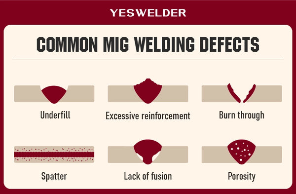
Porosity Solutions: Eliminating Gas Contamination Issues
Porosity in completed welds typically indicates insufficient shielding gas coverage. Diagnose systematically by checking:
- Gas flow rates at the regulator (15-50 CFH depending on application)
- Gas delivery system for leaks (use soapy water on connections)
- Nozzle condition and cleanliness (spatter buildup restricts flow)
- Gas selection for your base material
Quick Fix: Increase gas flow by 5 CFH and clean your nozzle thoroughly. If porosity persists, check for wind interference or consider using a larger nozzle diameter for better gas coverage.
Lack of Fusion: Adjusting Parameters for Proper Bonding
Lack of fusion results from insufficient heat input, which may stem from:
- Low amperage settings (too slow wire feed speed)
- Excessive travel speed
- Poor joint preparation
- Improper wire extension
To resolve lack of fusion:
1. Increase wire feed speed by 10-20 IPM
2. Reduce travel speed slightly
3. Verify proper joint fit-up (gap should be appropriate for material thickness)
4. Check wire extension length (3/8-5/8 inch typically)
Safety Essentials: Protecting Yourself During MIG Operations
Electrical and Respiratory Protection
MIG welding equipment operates at significant voltage levels (20-480 volts), creating electrical shock hazards. Always:
- Ensure dry conditions underfoot
- Insulate yourself from grounded surfaces
- Regularly inspect cables and connections for damage
Welding generates hazardous fumes requiring proper respiratory protection. Fume extraction systems provide the most effective protection, while respirators may be necessary in confined spaces. Stainless steel and galvanized steel produce particularly hazardous fumes requiring enhanced protection measures.
Radiation and Burn Prevention
The MIG welding arc produces intense ultraviolet radiation that can cause severe eye damage within seconds. Always wear:
- Welding helmet with appropriate shade lens (shade 10-12 for MIG)
- Flame-resistant gloves, jacket, and apron
- Safety glasses under your helmet
Nearby personnel require the same protection—use welding screens or curtains in shared work areas to prevent inadvertent exposure to passersby.
Final Takeaways: Mastering MIG Welding Fundamentals
How does MIG welding work? Through the coordinated interaction of electrical energy, consumable wire electrode, and shielding gas to create strong metallurgical bonds between metal pieces. The power source converts incoming electricity into controlled direct current, while the wire feed mechanism continuously delivers electrode material to the weld pool. Shielding gas protects the molten metal from atmospheric contamination, and your technique controls how heat is applied and where filler metal is deposited.
This combination produces a welding process remarkable for its versatility, efficiency, and accessibility. From thin automotive panels to thick structural steel, MIG welding adapts to applications across the entire spectrum of metal fabrication. Understanding the fundamental principles—how shielding gas protects the weld pool, the relationship between wire feed speed and heat input, and the characteristics of different transfer modes—enables you to select appropriate parameters, troubleshoot problems, and consistently produce high-quality welds across a wide range of applications and materials.
Pro Maintenance Tip: Replace consumables regularly—contact tips typically last 4-8 hours of welding time. Signs of wear include erratic arc behavior, increased spatter, and wire feeding problems. Keeping spare consumables on hand prevents workflow interruptions during critical projects.
Leave a Reply