Ever wondered how aerospace engineers join titanium components with surgical precision or how medical device manufacturers create flawless hermetic seals? The answer lies in plasma welding, a sophisticated process that transforms ordinary gas into the fourth state of matter to create some of the cleanest, strongest welds in manufacturing. Understanding how plasma welding work reveals a remarkable fusion of physics and engineering where temperatures exceed 30,000°C—hotter than the sun’s surface—yet delivers unprecedented control for delicate applications. This advanced technique has become indispensable across industries where weld integrity directly impacts safety and performance, from aircraft engines to surgical implants.
Unlike conventional arc welding where the electrical arc moves freely, plasma welding constricts this arc through a precisely engineered nozzle, creating a focused jet of ionized gas that delivers exceptional penetration with minimal heat distortion. The result is welds so clean they often require no post-weld cleanup—no spatter, no slag, and a narrow heat-affected zone that preserves material properties. Whether you’re a welding professional evaluating new techniques or simply curious about this remarkable technology, this guide explains exactly how plasma welding work while providing actionable insights you can apply immediately.
The Plasma Arc: From Gas to Fourth State of Matter
Plasma welding works by transforming ordinary gas into plasma—the fourth state of matter—through ionization. When sufficient electrical energy passes through a gas like argon, electrons separate from their atoms, creating a mixture of ions, electrons, and neutral particles that conducts electricity with extraordinary efficiency. This ionization process occurs within the welding torch where a tungsten electrode and copper nozzle create the perfect environment for plasma generation.
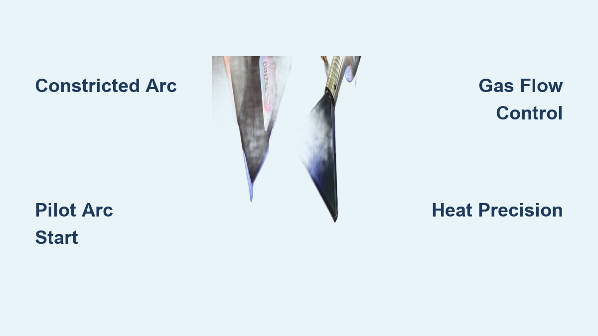
The magic happens when the pilot arc ionizes the plasma-forming gas flowing around the tungsten electrode. As this gas passes through the constricting nozzle orifice, it becomes a focused plasma jet reaching temperatures between 10,000-30,000°C. You’ll notice this extreme heat concentration allows plasma welding to melt through thick materials while maintaining a weld bead as narrow as 0.5mm for delicate applications. Argon serves as the primary plasma gas due to its stable ionization characteristics, though hydrogen or helium additions modify thermal properties for specific materials.
What makes plasma welding work so effectively is how this constricted arc maintains stability unmatched by conventional processes. The nozzle physically confines the arc, preventing wandering and ensuring consistent energy delivery regardless of minor technique variations. This stability enables precise control over heat input—critical when welding heat-sensitive materials like titanium alloys in aerospace components where distortion could compromise structural integrity.
Inside the Plasma Welding Torch: Critical Components Explained
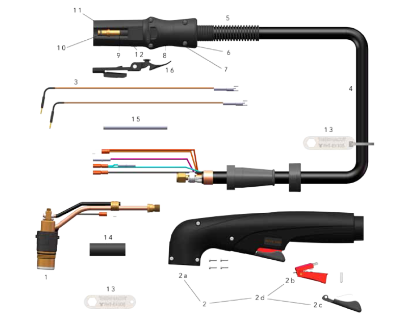
Your plasma welding torch contains several precision-engineered components working in concert to generate that remarkable plasma arc. The tungsten electrode—typically thoriated for enhanced electron emission—serves as the cathode, positioned precisely relative to the copper nozzle that functions as the anode. Copper’s exceptional thermal conductivity allows the nozzle to withstand extreme temperatures while maintaining the critical orifice shape that constricts the plasma jet.
The nozzle orifice diameter directly determines your plasma jet’s characteristics: smaller openings create more concentrated, higher-velocity streams ideal for thin materials, while larger orifices produce broader heat patterns for thick-section welding. You must maintain proper electrode-to-nozzle alignment—typically 1-3mm spacing—to ensure optimal arc stability. Even minor misalignment causes erratic plasma formation and inconsistent weld quality.
Water cooling channels surrounding these components prove essential for sustained operation. Without adequate cooling, the extreme heat would quickly damage the torch. Modern systems incorporate flow sensors that automatically shut down the welder if coolant circulation fails. When maintaining your equipment, regularly inspect the nozzle for erosion or spatter buildup—damaged components disrupt plasma formation and should be replaced immediately to maintain weld quality.
Pilot Arc vs. Transferred Arc: Understanding Plasma Welding Modes
Plasma welding work through a sophisticated dual-arc system that distinguishes it from other processes. The pilot arc operates continuously between the tungsten electrode and nozzle, maintaining ionization even when not actively welding. This ready-state plasma allows instant arc transfer when you bring the torch near the workpiece—no high-frequency restriking needed like in TIG welding.
When the plasma jet contacts the conductive workpiece, the arc transfers from the pilot circuit to the welding circuit. At this critical moment, full welding current flows through the plasma column to your workpiece. You’ll operate primarily in transferred arc mode for most welding applications, where the direct electrical connection provides deeper penetration and higher energy transfer efficiency. This mode delivers the signature narrow, deep weld beads with minimal heat distortion.
Non-transferred arc mode keeps the circuit contained within the torch, heating the workpiece purely through thermal energy transfer. You’d use this mode for non-conductive materials or surface treatments where electrical effects on the workpiece must be avoided. The transition between modes depends on maintaining proper arc length—typically 3-6mm from nozzle to workpiece. Too far, and the arc extinguishes; too close, and you risk nozzle damage from spatter.
Gas Dynamics: How Plasma and Shielding Gases Interact for Perfect Welds

The gas flow dynamics in plasma welding work through a carefully balanced system where plasma gas forms the arc while shielding gas protects the weld pool. Plasma gas flows at 0.5-15 L/min through the constricting nozzle, with flow rate precisely matched to your welding current. Too little gas causes arc instability and accelerated electrode wear; too much disrupts the plasma column and reduces penetration depth.
Shielding gas—typically argon or argon-helium mixtures—flows at higher rates (10-30 L/min) through an outer nozzle, creating a protective envelope around the molten weld pool. You’ll notice the interaction between the high-velocity plasma jet and slower shielding gas creates complex flow patterns that influence weld pool dynamics. Hydrogen additions (5-15%) to the plasma gas dramatically increase thermal conductivity for deeper penetration in stainless steel applications.
When setting up your plasma welding system, consider these critical gas relationships:
– Pure argon provides stable arcs for most applications
– Argon-hydrogen blends enhance penetration in nickel alloys
– Helium additions raise arc temperatures for faster travel speeds
– Nitrogen can improve penetration in copper but risks embrittlement
Improper gas balance causes common issues like porosity from atmospheric contamination or irregular bead shapes from turbulent flow patterns. Always verify gas purity—contaminated supplies introduce moisture or oxygen that degrades weld quality immediately.
Heat Transfer Secrets: How Plasma Energy Melts Metal So Precisely
Plasma welding work through three distinct heat transfer mechanisms operating simultaneously. Conduction dominates as thermal energy flows from the plasma impact point into surrounding material according to temperature gradients. You’ll achieve exceptionally narrow heat-affected zones because the constricted arc creates steep thermal gradients that localize heating to the immediate weld area.
Convective heat transfer becomes significant within the molten weld pool itself, where fluid flow distributes heat according to surface tension variations and plasma jet impact. The high-velocity plasma stream creates additional flow patterns you can exploit to control bead shape—increasing travel speed pulls molten metal rearward for flatter beads, while slower speeds allow more radial flow for convex profiles.
Radiative heat transfer contributes substantially at plasma temperatures exceeding 10,000°C. Both plasma column and molten pool emit thermal radiation that heats surrounding areas, particularly important when welding low-conductivity materials like titanium. The energy transfer efficiency of plasma welding (50-80%) significantly exceeds conventional processes, explaining why you achieve faster travel speeds with less distortion. This efficiency stems directly from the constricted arc design that minimizes atmospheric energy losses.
5 Essential Plasma Welding Parameters You Must Control
Mastering plasma welding work requires precise control over these interconnected parameters:
Welding current serves as your primary heat input control. Higher currents produce deeper penetration and wider beads but require proportional increases in gas flow. Micro-plasma applications use less than 10A for delicate work, while heavy industrial welding exceeds 500A.
Plasma gas flow rate must balance with current to maintain arc stability. The relationship isn’t linear—you’ll need to increase flow more than proportionally at higher currents to prevent nozzle overheating.
Travel speed determines heat input per weld length. Faster speeds reduce distortion but risk lack of fusion; slower speeds increase penetration but expand heat-affected zones. Find your sweet spot through test welds on scrap material.
Arc length (nozzle-to-work distance) critically affects voltage and bead shape. Shorter arcs concentrate heat for maximum penetration; longer arcs spread energy for wider beads. Maintain consistent distance—variations of just 1mm cause noticeable quality changes.
Torch angle influences weld pool dynamics. Perpendicular (90°) angles work for most applications, but slight trailing angles (5-15°) improve penetration in keyhole welding while leading angles help with melt-in mode bead control.
Micro to Keyhole: Different Plasma Welding Techniques for Different Jobs
Plasma welding work across multiple operational modes tailored to specific applications. Micro-plasma welding (under 10A) creates weld beads as narrow as 0.5mm for thin materials like surgical tubing. You’ll appreciate its stability when joining delicate components where heat input must be precisely controlled.
Medium-current plasma (10-100A) represents the workhorse for general fabrication. This versatile mode handles most material thicknesses with excellent control over penetration and bead shape—ideal for aerospace components and pressure vessels where weld integrity is critical.
High-current plasma (over 100A) delivers full-penetration welds in thick materials at impressive speeds. You’ll need larger torches with enhanced cooling, but the payoff is single-pass welds in materials requiring multiple passes with other processes.
Keyhole plasma welding exploits extreme energy density to create a vapor cavity completely through the material. As you travel along the joint, molten metal flows around this keyhole and solidifies behind it—perfect for single-pass welds in thick sections.
Melt-in mode produces welds without keyhole formation, similar to TIG but with superior arc stability. Use this for root passes or thinner materials where complete penetration isn’t required.
Why Plasma Wins: Key Advantages Over TIG and MIG Welding
When you understand how plasma welding work compared to alternatives, its advantages become clear. The constricted arc provides inherent stability that surpasses TIG welding, reducing sensitivity to technique variations and magnetic arc blow. This stability proves invaluable for automated systems where consistent parameters determine production quality.
Plasma’s high energy density enables deeper penetration with narrower beads than TIG, reducing weld metal volume and heat-affected zone size. You’ll achieve 30-50% faster travel speeds on comparable materials while minimizing distortion in heat-sensitive components.
Unlike MIG welding, plasma produces virtually no spatter since the molten metal heats through thermal transfer rather than direct electrical contact. This eliminates time-consuming post-weld cleanup and reduces or eliminates grinding requirements.
The process handles an exceptional material range, from 0.1mm foil to 25+ mm thick sections with the same equipment configuration. You can weld virtually any metal used in industrial applications—from aluminum and steel to exotic alloys like Inconel and titanium—with appropriate parameter adjustments.
Most importantly, plasma welding delivers superior weld quality with minimal defects. The focused heat input, consistent shielding, and stable arc produce clean, spatter-free welds that often meet stringent aerospace and medical standards without additional processing.
Mastering how plasma welding work unlocks capabilities impossible with conventional techniques. By harnessing the fourth state of matter through precise engineering, you gain unmatched control over heat input, penetration, and weld quality—critical for applications where failure isn’t an option. While the equipment demands higher initial investment and parameter precision, the payoff comes in cleaner welds, reduced post-processing, and the ability to join challenging materials with confidence. As you implement these techniques, remember that consistent results come from understanding the relationship between gas dynamics, electrical parameters, and thermal transfer. Start with test welds to dial in your settings, maintain your torch components rigorously, and always prioritize safety with proper radiation protection. The precision and quality achievable through plasma welding make it worth the learning curve for any serious fabricator tackling high-value, mission-critical welding applications.
Leave a Reply