When molten metal meets oxygen during welding, the result is often disastrous—porous, brittle welds that fail under pressure. This is why understanding how is argon used in welding has become non-negotiable for professionals across industries. As an inert gas that refuses to react with other elements, argon creates the protective bubble necessary for clean, strong welds. Whether you’re fabricating aircraft components or repairing farm equipment, argon’s shielding properties prevent atmospheric contamination that would otherwise ruin your work. From TIG welding aluminum bicycle frames to MIG welding steel truck frames, this noble gas forms the invisible barrier between success and scrap metal.
The question of how is argon used in welding matters because one wrong gas choice can compromise an entire project. In automotive manufacturing alone, improper shielding gas selection causes millions in rework annually. This guide cuts through the confusion by detailing exactly when and how to deploy argon for optimal results across different metals and processes. You’ll discover specific argon mixtures for stainless steel versus aluminum, learn flow rate calculations that prevent costly contamination, and master troubleshooting techniques for common shielding gas issues. By the end, you’ll understand why 90% of professional welders consider argon indispensable in their gas cabinets.
Why Argon Prevents Weld Contamination
Argon creates an impenetrable barrier between molten metal and atmospheric gases that cause immediate weld failure. Three contaminants pose critical threats: oxygen forms brittle oxides that create microscopic cracks, nitrogen produces hard nitrides that reduce ductility, and moisture introduces hydrogen that causes delayed cracking in high-strength steels. Unlike reactive gases, argon’s full electron shell means it remains chemically stable even at 10,000°F welding temperatures, providing consistent protection from arc ignition to final solidification.
Critical contamination thresholds you must avoid:
– Oxygen content above 0.05% causes visible oxidation
– Nitrogen levels exceeding 0.02% create embrittlement
– Moisture content over 20 ppm risks hydrogen cracking
The heavier-than-air density of argon (1.4 times air’s density) allows it to blanket the weld pool effectively. However, this same property means wind speeds over 5 mph can disrupt shielding coverage. Always increase flow rates by 25% when welding outdoors or in drafty workshops to maintain adequate protection. Watch for the characteristic “gas cone” extending at least ½ inch beyond the weld pool—if you can’t see this visible boundary, your shielding is inadequate.
Pure Argon Applications in TIG Welding
Aluminum Welding with 100% Argon
Pure argon delivers the clean, oxide-free welds required for aluminum fabrication where even microscopic contamination causes failure. The alternating current (AC) TIG process relies on argon’s stability to maintain arc consistency during the electrode-positive cleaning cycle that removes aluminum oxide. For thin sheet metal under 1/8 inch, use 15-20 CFH flow rates with a #12 cup to prevent turbulence. Thicker sections above ¼ inch require 25-35 CFH with a #17 cup to protect the larger molten pool.
Critical mistake to avoid: Using argon with excessive flow rates on aluminum causes atmospheric entrainment through turbulence. If your welds show gray discoloration or surface pitting, reduce flow by 5 CFH increments until the weld pool remains bright and fluid.
Stainless Steel TIG Welding Techniques
Pure argon preserves the corrosion resistance of stainless steel by preventing chromium oxidation at the weld surface. For 304 and 316 grades under 1/4 inch thick, maintain 18-22 volts with 200-250 amps using 2% lanthanated tungsten. The argon shield must cover both front and back sides of the weld—use trailing gas cups or purge fixtures for critical applications like pharmaceutical piping. Flow rates between 20-25 CFH work for most stainless steel TIG, but increase to 30 CFH when welding in vertical or overhead positions where gravity pulls the shielding gas away.
Argon Mixtures for MIG Welding Steel
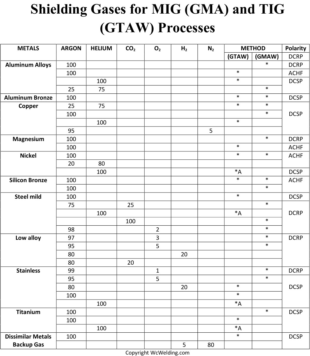
75% Argon/25% CO₂ for General Fabrication
This industry-standard mixture combines argon’s arc stability with CO₂’s penetration power. The 75/25 blend works across material thicknesses from 18-gauge sheet metal to ½ inch plate when you adjust parameters correctly:
- Thin materials (18-14 gauge): 16-18 volts, 180-220 ipm wire feed
- Medium thickness (1/8-3/16 inch): 19-21 volts, 230-270 ipm
- Thick sections (¼ inch+): 22-24 volts, 280-320 ipm
Maintain 35-40 CFH flow rates with this mixture—lower rates won’t protect the larger MIG weld pool, while higher flows create turbulence. The distinctive “sizzle” sound of proper metal transfer indicates optimal shielding. If you hear popping or see excessive spatter, check for leaks in your gas delivery system before adjusting flow rates.
90% Argon/10% CO₂ for Thin Material Welding
This high-argon blend produces the smoothest bead appearance with minimal spatter on thin metals. Use it for automotive body panels, HVAC ductwork, or any application where post-weld grinding isn’t feasible. For 22-gauge steel, set parameters to 14-16 volts with 150-180 ipm wire feed using 0.023″ wire. Flow rates should stay between 30-35 CFH—any higher and the delicate arc becomes unstable. The trade-off is reduced penetration, so avoid this mixture for structural joints over 1/8 inch thick.
Specialized Argon Mixtures for Exotic Metals
Titanium Welding with Ultra-High Purity Argon
Titanium demands 99.999% pure argon to prevent embrittlement from trace oxygen. Any discoloration beyond straw yellow indicates contamination—blue or gray welds must be cut out completely. Use 25-30 CFH flow with trailing shields that extend argon coverage for 30 seconds after arc extinguishing. For critical aerospace applications, add 2-4% helium to increase heat input without sacrificing protection. Always use dedicated regulators and hoses that have never contacted other gases to prevent cross-contamination.
Copper Welding with Argon-Helium Blends
Copper’s extreme thermal conductivity requires 75% argon/25% helium to maintain adequate heat in the weld zone. This mixture increases arc temperature by 1,000°F compared to pure argon, preventing premature solidification. Preheat copper to 500-1,000°F depending on thickness, then use 25-35 CFH flow with 20-25% higher amperage than steel. Watch for the characteristic “wet” appearance of properly shielded copper welds—if the pool looks grainy or oxidized, increase helium content to 50%.
Optimal Flow Rates by Welding Process
GTAW Flow Rate Guidelines
Your argon flow rate must balance coverage and turbulence. Use these industry-proven standards:
- Thin materials (<1/8 inch): 15-20 CFH
- Medium thickness (1/8-3/8 inch): 20-25 CFH
- Thick sections (>3/8 inch): 25-35 CFH
- Drafty conditions: Add 25% to standard rates
The cup size directly affects coverage—larger cups require higher flows. A #10 cup needs 15 CFH while a #17 cup requires 30 CFH for equivalent protection. Always perform a visual check: proper shielding shows a steady, laminar gas flow extending ½ inch beyond the tungsten tip without swirling.
GMAW Flow Rate Optimization
MIG welding demands higher flows due to faster travel speeds:
- Short-circuit transfer: 30-35 CFH
- Globular transfer: 35-40 CFH
- Spray transfer: 40-45 CFH
- Pulsed spray transfer: 35-40 CFH
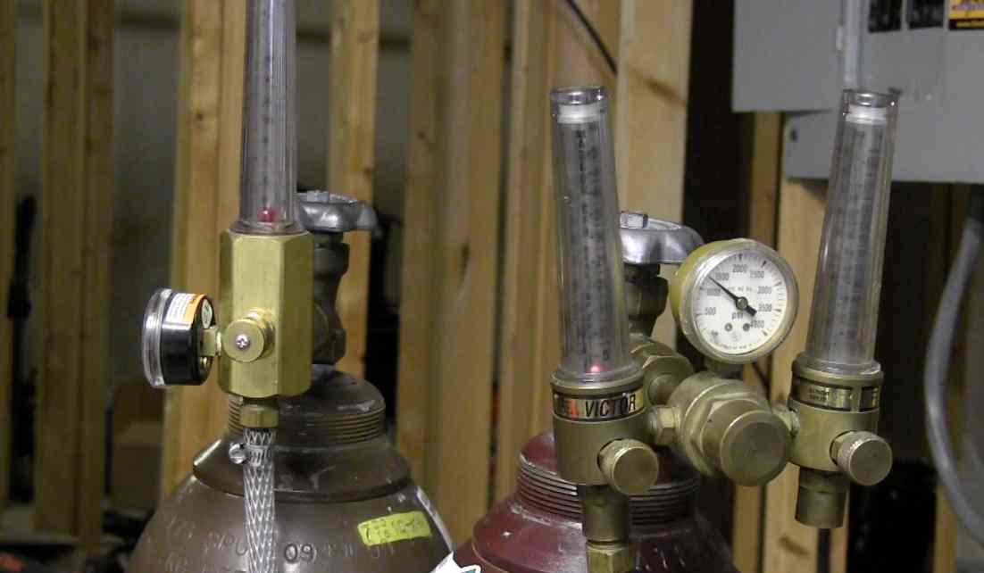
Measure flow at the torch—not the regulator—as line restrictions reduce actual delivery. Install flow meters directly at the gun for critical applications. If your welds show porosity despite correct parameters, increase flow by 5 CFH increments until defects disappear, but never exceed 50 CFH as turbulence will worsen contamination.
Troubleshooting Common Argon-Related Defects
Fixing Porosity in Aluminum Welds
Porosity appears as tiny holes throughout the weld bead and stems from inadequate argon coverage. First, verify your flow rate matches material thickness—15 CFH works for thin sheet but fails on thick plate. Next, check for leaks in the gas system using soapy water on all connections. If problems persist, switch to argon with 25% helium for better coverage on thick aluminum sections. Always clean aluminum immediately before welding, as oxide reforming during welding consumes shielding gas.
Eliminating Spatter with Argon Mixtures
Excessive spatter often indicates incorrect gas composition rather than machine settings. For steel welding, if you’re using pure CO₂, switch to 75% argon/25% CO₂ to reduce spatter by 60-70%. Ensure your flow rate stays between 35-40 CFH—too little causes spatter from atmospheric contamination, while too much creates turbulence that draws in air. Replace worn contact tips immediately, as misaligned tips disrupt the shielding gas cone and cause erratic metal transfer.
Safety Protocols for Argon Handling
Preventing Oxygen-Deficient Atmospheres
Argon’s greatest hazard is its ability to displace oxygen without warning. In confined spaces, concentrations above 19.5% oxygen can cause unconsciousness in seconds. Always test oxygen levels with a calibrated meter before entering tanks or enclosed structures. Maintain ventilation that provides 200 CFM per welder in enclosed spaces. Never store argon cylinders in pits or basements where the heavy gas can accumulate. Install oxygen deficiency monitors in welding areas that sound alarms below 19.5% oxygen.
Proper Cylinder Storage Procedures
Store argon cylinders upright with valve protection caps secured. Keep them away from heat sources by at least 20 feet and separate from fuel gases by fire-resistant barriers. Never allow cylinders to reach temperatures above 130°F—direct sunlight can exceed this in minutes. Secure cylinders to prevent tipping, as a falling cylinder can shear the valve and become a dangerous projectile. Before use, crack the valve slightly to blow out contaminants, then attach a proper regulator designed for inert gases.
Cost-Saving Strategies for Argon Usage
Reducing Gas Waste with Flow Optimization
Most shops waste 20-30% of their argon through improper flow rates. Install flow meters at each welding station rather than relying on regulator gauges. For TIG welding, reduce flow by 5 CFH increments until weld quality declines, then increase by 2 CFH for safety margin. In MIG applications, use gas lens kits that improve gas coverage efficiency, allowing 10-15% lower flow rates. Implement gas saver valves that shut off flow during welding pauses—these pay for themselves in under 3 months for high-volume operations.
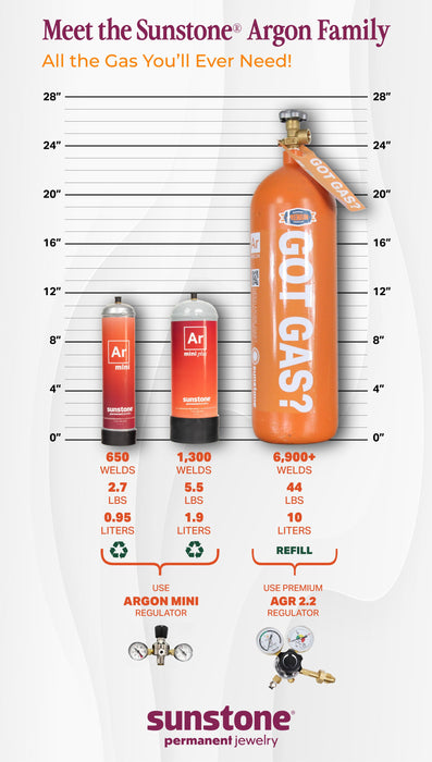
Bulk Delivery Versus Cylinder Management
Calculate your break-even point between cylinder and bulk delivery:
– Under 10 cylinders/week: Stick with cylinders
– 10-20 cylinders/week: Evaluate micro-bulk systems
– Over 20 cylinders/week: Switch to bulk delivery
Bulk argon costs 30-50% less per cubic foot than cylinder gas but requires significant infrastructure. For shops using 5+ cylinders weekly, portable liquid dewars offer intermediate savings without permanent installation. Always negotiate contracts based on annual usage—suppliers often provide better rates for committed volumes.
Understanding how is argon used in welding transforms theoretical knowledge into practical results that strengthen every joint you create. By matching argon purity, mixture ratios, and flow rates to your specific materials and processes, you eliminate preventable defects that waste time and materials. Remember that proper argon shielding isn’t an expense—it’s an investment that pays dividends through reduced rework, longer consumable life, and welds that pass inspection the first time. For immediate improvement, audit your current gas setup using the flow rate guidelines provided and implement one cost-saving strategy this week. The difference in your next project’s quality will prove why professional welders trust argon as their invisible partner in precision fabrication.
Leave a Reply