Those tiny molten metal droplets flying from your weld pool aren’t just annoying—they’re costing you time and money every single day. When spatter coats your workpiece, torch, and surrounding area, you’re forced into the tedious cycle of chipping, grinding, and prepping before moving to the next step. For professional fabricators, understanding exactly how to avoid spatter in welding isn’t optional—it directly impacts your bottom line through wasted labor hours and damaged equipment. Whether you’re working on automotive repairs or structural steel fabrication, spatter reduction should be at the top of your welding priority list.
This guide cuts through the confusion by giving you specific, actionable techniques that actually work. You’ll learn the precise electrical settings for your material thickness, discover why your shielding gas choice might be the hidden culprit, and implement maintenance practices that prevent spatter before it starts. Most importantly, you’ll gain the diagnostic skills to troubleshoot persistent spatter issues that continue despite “proper” settings.
Why Your Welds Are Covered in Metal Droplets (The Physics of Spatter)
Welding spatter consists of small molten metal droplets violently expelled from the weld pool during the welding process. This happens when expanding gases trapped in the superheated weld pool combine with electromagnetic forces and surface tension variations to propel metal away from the joint. The severity depends entirely on how unstable this delicate balance becomes during welding.
Excessive spatter creates cascading problems beyond cosmetic concerns. Spatter accumulation on your torch disrupts wire feed consistency, causing arc instability that generates even more spatter. Contact tips become fouled, leading to irregular wire feeding that compounds the problem. On the workpiece, spatter requires grinding or chipping before painting or coating, significantly increasing fabrication time. Adjacent fixtures and jigs suffer cumulative damage from repeated spatter exposure, creating replacement costs that add up over time.
Voltage and Wire Feed Speed: Your First Line of Defense Against Spatter
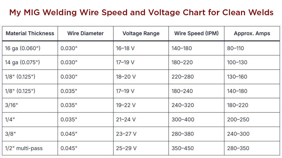
For carbon steel MIG welding, improper voltage and wire feed speed account for 70% of all spatter problems. When voltage runs too high, the arc length becomes excessive, causing the wire to melt too quickly and creating an unstable transfer mode. Conversely, voltage set too low causes the wire to stub directly into the workpiece, creating explosive transfer that violently ejects molten metal.
Finding the Perfect Voltage-Wire Feed Balance for Your Material Thickness
For short-circuiting transfer on materials thinner than 1/8 inch, voltage settings typically range from 15 to 19 volts. The goal is achieving a crisp, regular crackling sound indicating consistent short-circuiting cycles. Erratic or hissing sounds suggest voltage is too low, while popping sounds indicate voltage is too high. Make adjustments in small increments—large parameter changes often overcorrect and introduce new issues.
How Inductance Settings Can Make or Break Your Spatter Control
Inductance controls the rate of current rise during short-circuiting transfer. Higher inductance creates a more gradual current rise, producing a softer arc with less spatter. Lower inductance causes sharper current transitions that make metal transfer more aggressive. Finding the optimal setting requires balancing spatter reduction against penetration requirements—most applications benefit from medium-high inductance settings.
Shielding Gas Mixtures That Actually Reduce Spatter (Not Increase It)
Your shielding gas choice directly determines arc stability and metal transfer characteristics, making it one of the most effective spatter reduction strategies available. Pure carbon dioxide produces a deeply penetrating arc but generates significantly more spatter than argon-based mixtures due to turbulent arc characteristics and higher thermal conductivity.
Why 75% Argon/25% CO2 Beats Pure CO2 for Most Steel Welding
A 75% argon / 25% CO2 mixture (C25) provides the ideal balance of spatter reduction, penetration, and cost for most steel welding applications. This mixture produces a noticeably smoother arc than pure CO2, and the reduction in cleanup time often justifies the slightly higher gas cost. For critical applications where appearance matters most, an 80% argon / 20% CO2 mixture offers further improvement at increased expense.
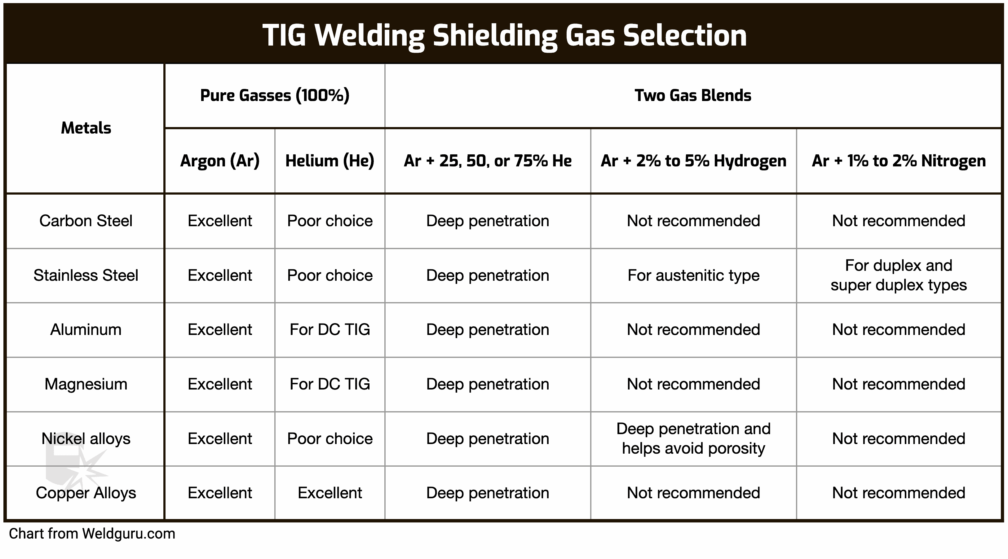
Special Gas Mixtures for Stainless Steel and Aluminum Welding
Stainless steel requires specialized gas mixtures (typically argon with 2-5% CO2 and 1-2% oxygen) to maintain corrosion resistance while minimizing spatter. Aluminum welding demands pure argon or helium-argon mixtures—helium increases penetration but also increases spatter potential, requiring careful parameter balancing. Using improper gas on these materials causes both spatter problems and compromised weld properties.
The Critical Base Metal Cleaning Process Most Welders Skip
Surface contamination on base metal introduces impurities that disrupt normal metal transfer and promote spatter formation. Rust, mill scale, oil, grease, paint, and even invisible contamination layers alter surface tension in the molten weld pool and introduce gases that become trapped during solidification.
How Invisible Contaminants Cause More Spatter Than You Realize
A seemingly clean surface may still produce excessive spatter due to residues invisible to the naked eye. Wire brushing with a dedicated clean brush removes rust and scale, while solvent cleaning eliminates oil and grease. For critical welds, grinding or machining to remove surface defects provides a clean starting point. Always inspect both base metal and filler wire immediately before welding—condensation can form when moving between temperature environments.
Proper Filler Wire Storage Techniques to Prevent Spatter
Wire exposed to moisture causes hydrogen-related issues that destabilize the arc. Store wire in dry environments and cover spools when not in use. Before loading wire, inspect the first few inches for contamination or damage. Keep wire feed rollers clean and properly adjusted to prevent wire deformation that causes feeding problems and subsequent spatter.
Torch Handling Secrets for Spatter-Free Weld Beads
Maintaining proper torch angle throughout the weld bead significantly reduces spatter generation. For flat position welding on carbon steel, a push angle of 10 to 15 degrees from perpendicular generally produces excellent results. This angle directs arc forces into the weld pool while maintaining shielding gas coverage. The angle should remain consistent rather than varying randomly.
The Exact Push Angle That Minimizes Spatter in Flat Position Welding
A consistent 10-15 degree push angle keeps the arc directed into the leading edge of the weld pool while maintaining optimal shielding gas coverage. Angles beyond 20 degrees expose the weld pool to atmospheric contamination, while angles less than 5 degrees cause the arc to push molten metal ahead of the weld pool, increasing spatter likelihood.
How Travel Speed Affects Spatter More Than You Think
Travel speed should match joint design and material thickness. As a starting point, travel speed that produces a weld bead width approximately three times the wire diameter provides adequate penetration without excessive heat input. Faster travel speeds reduce heat input and can minimize spatter but sacrifice penetration if too aggressive. Slower speeds cause excessive heat buildup that enlarges the weld pool and increases spatter susceptibility.
Wire Feed System Maintenance Checklist to Eliminate Spatter
The wire feed system requires regular maintenance to ensure consistent wire delivery that prevents spatter. Wire feed rollers must match the wire diameter and type, with appropriate groove shape and hardness. Worn or incorrectly sized rollers deform the wire, causing inconsistent feed rates that lead to arc instability and spatter.
Why Roller Tension Settings Cause 30% More Spatter Than Properly Adjusted Systems
Roller tension requires careful adjustment to provide adequate grip without excessive pressure that deforms the wire. Insufficient tension causes slippage producing irregular wire feed and inconsistent arc. Excessive pressure flattens the wire, particularly with soft materials like aluminum, causing feeding problems that translate into spatter. Adjust tension until wire feeds smoothly without deformation.
Liner Replacement Frequency That Prevents Intermittent Feeding Problems
Liner replacement is frequently overlooked but critically important for consistent wire feeding. Worn or contaminated liners increase feeding resistance, causing irregular wire speed that translates into arc instability and spatter. Replace liners every 3-6 months or immediately when feeding problems develop, always using the correct liner type for your wire diameter and material.
Troubleshooting Persistent Spatter When Everything Else Checks Out
/ABIBLOG%20BRASIL/7%20most%20common%20Welding%20Defects%20and%20how%20to%20solve%20them/blog_welding_defects_spatter_01.png?width=283&name=blog_welding_defects_spatter_01.png)
When spatter persists despite proper basic parameters and technique, systematic diagnosis identifies the root cause. Observe arc behavior and listen to arc sounds for immediate process stability feedback. Unstable arc with erratic popping sounds indicates electrical problems or parameter mismatch.
How Wind Speeds Under 5 MPH Can Ruin Your Shielding Gas Coverage
Wind and drafts disrupt shielding gas coverage, causing atmospheric contamination that increases spatter. Wind speeds as low as five miles per hour can compromise shielding in open environments. Use windshields, screens, or enclosed areas when welding outdoors or in drafty conditions. Cold base metal increases heat dissipation, potentially requiring higher heat input—preheating cold base metal improves consistency and reduces spatter.
Five-Step Spatter Prevention System for Consistent Results
- Verify electrical parameters – Match voltage to wire feed speed for your wire diameter and material thickness
- Select appropriate shielding gas – Use 75% argon/25% CO2 for most steel applications
- Prepare surfaces meticulously – Remove all contaminants from base metal and filler wire
- Maintain proper technique – Keep consistent torch angle (10-15° push) and travel speed
- Perform regular equipment maintenance – Clean wire feed system and replace consumables on schedule
By implementing these specific strategies, you’ll transform your welding operation from one plagued by constant spatter cleanup to a streamlined process with consistently clean welds. The time you save on grinding and chipping will quickly justify the minor adjustments to your parameters and procedures. Remember that avoiding welding spatter isn’t about finding one magic setting—it’s about understanding how all these factors interact to create the perfect welding environment for your specific application.
Leave a Reply