That frustrating moment when your perfectly measured parts shift during welding—sound familiar? Learning how to build a jig for welding transforms inconsistent manual fabrication into reliable, repeatable manufacturing. Whether you’re producing motorcycle frames, automotive chassis, or simple right-angle assemblies, a well-designed jig holds workpieces in precise alignment, ensuring every weld lands exactly where it should. The investment in jig construction pays dividends immediately—setup time drops dramatically, rework from misalignment becomes rare, and the parts you produce interchange consistently. This guide walks you through selecting materials, designing your layout, constructing the jig, and protecting your investment for years of productive shop use.
The decision to build a custom jig depends entirely on production volume and the complexity of your workpieces. For one-off projects, the time spent constructing a jig often exceeds the time saved during fabrication. However, when producing multiple identical pieces—even just three or four—a jig quickly pays for itself by eliminating repeated measurement, adjustment, and correction. A simple right-angle fixture might take an evening to construct and save fifteen minutes on every subsequent assembly. A complex chassis jig might require fifty hours of labor but enables accurate repairs that would otherwise be impossible to achieve.
Select the Right Base Material for Your Welding Jig

Your jig’s foundation determines its durability, accuracy, and versatility. Choosing wisely prevents wasted time and frustration down the road when your jig fails during critical production.
MDF and Plywood for Budget-Friendly Jigs
Medium Density Fiberboard (MDF) offers an excellent entry point for fabricators new to jig construction. MDF costs mere dollars per sheet, remains dimensionally stable through humidity changes, and critically, won’t support combustion unless directly exposed to open flame. This fire resistance makes it suitable for MIG welding applications where occasional spark exposure occurs. The primary limitation? Workpieces must be screwed to the base, requiring drilling and countersinking holes for each configuration. Additionally, MDF doesn’t conduct electrical current, so you’ll need to move the work clamp to different positions as welding progresses.
Plywood provides greater structural strength and impact resistance compared to MDF. High-density plywood withstands frequent clamping and repositioning better than fiberboard. Professional rail fabricators often use steel-framed tables topped with laminated 2×4 wood members covered with 5/8-inch plywood. Chalk lines establish layout positions, and locating nails with clipped-off heads position pipe or tubing for fishmouth joints. Expect plywood surfaces to last approximately one year before spatter damage and burn-through require replacement.
Steel Plate for Heavy-Duty Production Jigs
When building a jig for high-volume production, steel plate provides the ideal substrate. For jigs up to approximately 24 inches by 24 inches, 1/4-inch plate resists warping adequately while remaining manageable for handling. Larger fixtures benefit from 3/8-inch plate for additional rigidity. Cast iron offers superior dimensional stability compared to steel when heated, making it the choice for precision work where heat distortion must be minimized.
Pro Tip: Surplus machine bases or surface plates in slightly worn condition can often be acquired at reasonable prices from industrial salvage sources. Aluminum tooling plate deserves consideration when tight tolerances are required—1-inch thick surplus aluminum provides excellent dimensional stability and weighs significantly less than steel, but avoid it when welding thick steel sections due to differential thermal expansion.
Design Your Jig Layout for Maximum Accuracy
A poorly designed jig wastes time and produces inaccurate parts. Follow these layout principles to ensure your jig delivers consistent results across multiple production runs.
Establish Reference Planes with Precision Tools
A surprisingly effective and inexpensive tool for establishing level reference is a red wine level gauge—clear plastic tubing filled with red wine. The physics of hydrostatic pressure ensures wine levels at each end reach identical heights regardless of distance between measurement points. Water proves less accurate due to excessive surface tension causing the liquid to stick inside the tube. This simple device enables achieving suspension mounting point accuracy of 0.5 millimeter relative to the jig reference plane.
Position your jig with adequate clearance from the floor to permit access for welding torches and angle grinders. Approximately 125 millimeters provides sufficient access for most welding and grinding operations while maintaining stability. During construction, level the jig by progressively thinner shims, checking with the wine level gauge until reference surfaces achieve required flatness.
Build Structural Rigidity to Prevent Twisting
The structural configuration directly impacts accuracy and longevity. C-section channel provides convenient mounting surfaces but offers minimal torsional stiffness—the jig will twist under load if not properly supported. When constructing chassis jigs or similar structures requiring rigidity, box section channel provides dramatically improved torsional resistance. A dedicated chassis jig for Renault 4 repair utilized 50mm by 100mm C-section channel with 6mm thickness for the center section and 9mm for top and bottom sections, though the designer noted that box section would have been preferable for stiffness.
Critical Mistake to Avoid: Locating parts by full surface contact rather than line contact allows spatter accumulation to alter setup accuracy over time. Design edges and datum surfaces to shed spatter rather than collecting it.
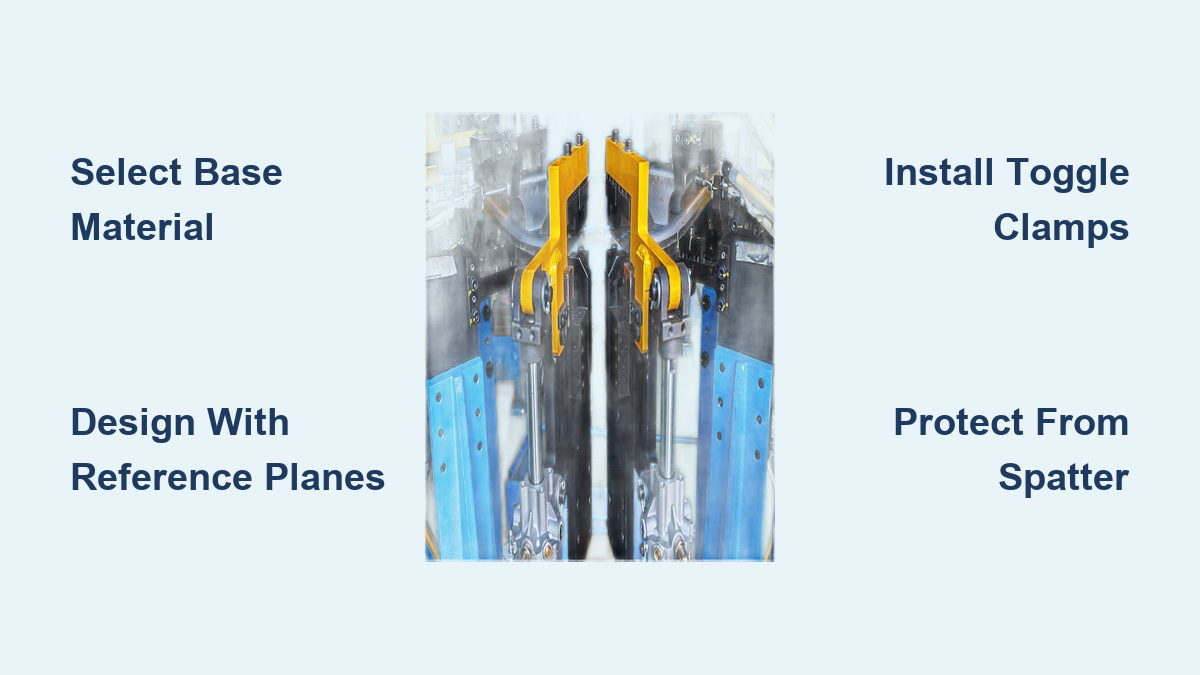
Install Effective Clamping Systems for Production Efficiency
Toggle clamps represent the workholding solution of choice for production welding jigs due to rapid operation and consistent clamping force. Destaco represents the premium brand, though generic alternatives available online for three to four dollars each provide adequate performance for most hobby applications.
Choose the Right Clamp Style for Your Workpiece
Horizontal hold-down clamps work well for flat parts, while vertical clamps accommodate taller workpieces. Spring-loaded clamps provide constant pressure during heat cycles when welding causes thermal expansion in the workpiece. Some fabricators modify inexpensive import clamps by cutting off factory ends and welding on 5/8-inch bolts to fit threaded holes in their jig tables, creating custom workholding at minimal cost.
Beyond conventional clamps, innovative fabricators develop custom solutions:
– Vise grips used in quantity provide versatile temporary clamping for complex assemblies
– Small custom clamps fabricated from scrap metal address specific workpiece geometries
– Wedges often prove more efficient than screw clamps for temporary positioning
Specialized Solutions for Round Stock Welding
For pipe and round tubing work, V-blocks provide stable positioning for drilling and welding operations. A V-block jig used with a drill press enables accurate hole placement in round stock. Pipe vises can be modified by welding hold-down brackets sized for specific pipe diameters, creating dedicated fixtures for common pipe welding tasks. Cast iron table saw extensions with factory-machined 90-degree corners can be cut down and repurposed as jig components, providing accurate reference angles at minimal cost.
Construct Your Basic Right-Angle Welding Jig
The most fundamental welding jig is the right-angle fixture, ensuring two pieces of metal meet at precisely 90 degrees during welding. Here’s how to build one:
- Position angle iron against the inside of a square reference
- Place a cross bar behind it at approximately the 3-inch mark
- Clamp the cross bar in position, flip the assembly, and place tack welds at four points
- Remove clamps and lay a full weld bead along the joint
- The diagonal cross bar maintains the 90-degree relationship until cooling
When tacking fixture components to a jig base, use a pull technique on horizontal surfaces and downward welding on vertical surfaces for best control. For MIG welding jig components, settings of approximately G-4 wire feed speed with 3/8-inch stick-out work well for tacking—each tack should last about one second to minimize heat input and distortion.
Protect Your Welding Jig During Production Runs
Using your completed jig for production welding requires protecting jig surfaces from spatter and heat damage to extend its useful life and maintain accuracy. WD-40 applied to jig surfaces before welding provides effective spatter protection while preventing rust formation on both jig and workpieces. The WD-40 doesn’t significantly affect MIG weld quality, and resulting welded joints remain shiny and rust-free.
Alternative spatter protection methods include:
– Commercial anti-spatter sprays (some promote rust in humid conditions)
– Ceramic nozzle coatings for long-lasting protection without mess
– Old motor oil applied with a paintbrush (avoid getting oil in the weld zone)
Maintain Your Jig for Long-Term Accuracy
Regular maintenance extends your jig’s useful life significantly. Compressed air effectively removes loose spatter between production runs, while periodic grinding may be necessary for accumulated deposits. Surfaces protected with WD-40 resist rust formation, maintaining functionality even in humid shop environments.
Jigs constructed from steel require attention to heat management during use. Design jigs to locate workpieces by edges and datum points rather than large surface areas, minimizing spatter accumulation and heat concentration. When jig components become damaged or worn beyond acceptable accuracy, they can often be repaired by grinding and re-welding, or replaced entirely while retaining the base plate.
When to Invest in Advanced Jig Construction
The economic justification for jig construction depends entirely on production volume. For fabricators producing motorcycle racks or crash guards, dimensional tolerance requirements allow jig construction using readily available materials without extreme precision measures. A jig that saves fifteen minutes per unit pays for itself quickly when producing dozens of identical pieces.
Permanent jigs for high-volume production warrant investment in premium materials and construction methods. Cast iron surface plates, precision-ground steel, and substantial toggle clamp arrays transform production operations but require corresponding investment. Build advanced jigs only when you have demonstrated production requirements—unused jig capacity represents significant opportunity cost.
Mastering how to build a jig for welding transforms inconsistent manual operations into reliable, repeatable manufacturing processes. Whether constructing a simple right-angle fixture or a complex chassis alignment jig, the principles of rigid construction, accurate reference establishment, and appropriate workholding remain consistent. Start with a basic jig for your most frequent project, and expand your jig collection as production demands grow—each new jig pays dividends through improved accuracy and reduced production time.
Leave a Reply