Connecting a welding machine correctly is essential for achieving clean, strong welds and maintaining a safe workshop environment. Whether you’re setting up a new MIG welder, configuring a TIG workstation, or hooking up a stick welding power source, the initial connection process determines your success with every bead you lay. This guide walks you through the essential steps to connect your welding machine properly, covering power requirements, grounding techniques, and safety precautions that protect both you and your equipment.
Before you strike your first arc, you need to understand that welding machines demand significant electrical power and present real hazards if improperly configured. A poorly connected welding machine can damage your equipment, produce inferior welds, create fire hazards, or expose you to dangerous electrical shock. Taking the time to connect everything correctly from the start saves frustration, money, and potential injury down the line.
Verify Your Power Supply Compatibility Before Making Connections

Your welding machine’s performance and safety depend entirely on matching it to the correct electrical supply. Many beginners make the critical mistake of plugging their machine directly into the first available outlet without checking specifications, which often leads to tripped breakers or equipment damage.
Match Machine Voltage Requirements to Your Workshop Circuits
Most hobbyist welding machines operate on either 110V or 220V household current, while industrial units may require 480V three-phase power. Locate your machine’s nameplate—typically found on the back panel or inside the wire compartment—which clearly states its voltage requirements. A common error occurs when users try to operate a 220V machine on a 110V circuit, resulting in weak performance and potential overheating. Conversely, connecting a 110V machine to a 220V circuit will almost certainly destroy the internal components immediately. Remember that 220V circuits require special outlets (like NEMA 6-50) that differ from standard household outlets, so never force a plug into an incompatible receptacle.
Calculate Circuit Load Capacity for Reliable Performance
Your welding machine’s amperage draw determines the circuit size it requires, and this specification appears on the nameplate alongside voltage requirements. For example, a typical 140-amp MIG welder requires a dedicated 30-amp circuit, while larger 200-amp machines need 50-amp circuits. Many workshop fires start because users share welding circuits with other high-draw tools like air compressors or table saws. To calculate your circuit’s capacity, multiply the breaker amperage by 0.8 (for continuous loads)—so a 30-amp breaker provides only 24 amps of continuous power. If your machine draws 28 amps at full capacity, it will constantly trip the breaker. When in doubt, hire a licensed electrician to install a dedicated circuit with proper wire gauge (typically 10-gauge for 30-amp circuits, 6-gauge for 50-amp).
Inspect Power Cord and Connection Points for Safety
Before making any connections, examine your welding machine’s power cord for frayed insulation, exposed wires, or damaged plugs. A compromised power cord creates serious shock and fire hazards that could electrocute you or ignite nearby materials. Pay special attention to the strain relief area where the cord enters the machine—a common failure point. If your machine uses a twist-lock plug (like NEMA L6-50), ensure the receptacle matches exactly and the plug locks securely into place. Never use extension cords with welding machines unless absolutely necessary, and if you must, choose a heavy-duty cord rated for the full amperage draw (typically 6-gauge for 50-amp machines). Long extension cords cause voltage drop that weakens your arc and may damage the machine’s internal components.
Establish a Secure Grounding System for Optimal Welding Performance
Proper grounding isn’t just a safety precaution—it’s essential for creating a stable electrical circuit that produces quality welds. Many welding problems stem from inadequate grounding rather than machine malfunctions, making this step critical for both safety and performance.
Position the Work Clamp for Maximum Electrical Conductivity
The work clamp (ground clamp) must connect directly to clean, bare metal on your workpiece or welding table. Paint, rust, oil, or other coatings create resistance that weakens your arc and produces inconsistent welds. Use a wire brush or angle grinder to remove coatings from the clamp area, creating a spot at least the size of a quarter. Position the clamp as close to your welding zone as possible—attaching it to the far end of a large workpiece creates resistance through the metal that degrades arc stability. For thick materials, consider using two ground clamps positioned on opposite sides of your weld area to create a more balanced electrical path. If you’re welding on a steel table, connect one clamp to the table frame and another directly to your workpiece for optimal conductivity.
Maintain Consistent Metal-to-Metal Contact During Welding
The clamp jaws must grip clean metal firmly throughout your welding session. Check periodically that the clamp hasn’t shifted or become loose, especially when working on hot metal that may expand and break contact. Spring-loaded clamps maintain better pressure than trigger-style clamps for stationary work. For production welding, magnetic grounding clamps provide instant positioning and consistent contact on flat surfaces. Inspect clamp jaws regularly for pitting, corrosion, or damage—if you see blue discoloration or deep grooves, replace the clamp immediately. A compromised clamp creates resistance that generates heat, potentially melting the clamp or creating hot spots on your workpiece that affect weld quality.
Ground Your Welding Table as a Separate Safety Measure
If you use a dedicated welding table, connect a separate grounding cable from the table frame directly to your machine’s grounding terminal. This creates a redundant grounding path that enhances safety and improves arc stability. Use welding cable (not ordinary electrical wire) of at least the same gauge as your work lead cable—typically 2/0 or 4/0 gauge for most hobbyist machines. Secure connections with proper lugs and crimp them tightly using a hydraulic crimper, then protect the connection points with heat-shrink tubing. This table ground operates independently from your work clamp ground but provides an additional safety path that prevents the table from becoming energized if your primary ground fails.
Configure Wire Feed and Gas Systems for MIG Welding Success
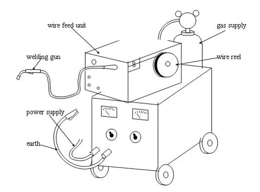
MIG welding requires precise coordination between wire feed, electrical current, and shielding gas—three systems that must work together seamlessly for quality welds. Proper connection and configuration prevent common problems like wire feeding issues, porosity, and inconsistent arc performance.
Thread Welding Wire Through the Feed System Correctly
Open the wire compartment and carefully thread the wire through the inlet guide, drive rollers, and outlet tube to the contact tip. Ensure the wire spool rotates freely in the correct direction (usually clockwise when viewed from above)—reversed spool rotation creates tension problems. Adjust the drive roller tension so the rollers grip the wire firmly without deforming it; too little tension causes slippage, while too much crushes the wire. Match the drive roller groove to your wire diameter (.023″, .030″, or .035″ are most common), and verify the polarity matches your wire type (DCEN for solid wire, DCEP for flux-cored). Before closing the compartment, cycle the wire feed mechanism to ensure smooth, consistent wire movement without kinks or resistance.
Set Initial Parameters for Your Material and Wire Size
Start with manufacturer-recommended settings based on your material thickness and wire diameter. For 18-gauge steel with .023″ wire, try 15-16 volts and 200-220 inches per minute wire speed; for 1/8″ steel with .035″ wire, try 19-20 volts and 250-270 IPM. These settings create the proper balance between wire feed speed and voltage—too much wire with insufficient heat causes excessive spatter and poor fusion, while too much heat with insufficient wire creates narrow, peaked beads with poor wetting. Make test welds on scrap metal of the same thickness as your project, adjusting voltage in 1-volt increments and wire speed in 10-IPM increments until you achieve consistent penetration and smooth bead appearance. Keep a settings chart near your machine for quick reference during future projects.
Connect and Test Your Shielding Gas System Thoroughly
Secure your gas cylinder to a wall or cart with a chain, then attach the regulator to the cylinder valve by hand-tightening the connecting nut—never use tools that could damage the threads. Open the cylinder valve slowly while watching the high-pressure gauge, then adjust the regulator knob to set flow rate between 20-30 CFH for most applications. Connect the gas hose from the regulator to your machine’s gas inlet, then attach the gun gas hose to the machine outlet. Before welding, perform a leak test by applying soapy water to all connections—bubbles indicate leaks that waste expensive shielding gas and create porous welds. For steel welding, use 75% argon/25% CO2 mix; for aluminum, use 100% argon. Always close the cylinder valve when not in use and release pressure from the regulator by opening the gun trigger briefly.
Complete Final Safety Checks Before Striking Your First Arc

Never skip these critical verification steps before powering up your welding machine—a few minutes of inspection prevents accidents and equipment damage.
Conduct a Comprehensive Connection Inspection
Walk through your entire setup examining every connection point. Verify power cord integrity, grounding cable security, gas line routing, and gun cable condition. Pay special attention to flex points where cables bend repeatedly—these areas develop fatigue failures that cause intermittent operation. Check that all electrical connections are tight and free of corrosion, and that grounding clamps contact clean metal securely. Inspect the welding gun for damaged insulation, cracked handles, or worn contact tips. Look for gas line kinks or pinches that restrict flow. This systematic inspection catches 90% of potential problems before they become hazards or equipment failures.
Prepare Your Workspace for Safe Welding Operations
Remove all flammable materials within a 35-foot radius of your welding area—this includes rags, solvents, cardboard, and wood scraps. Position a Class ABC fire extinguisher within immediate reach, and ensure proper ventilation to remove welding fumes. For indoor welding, use local exhaust ventilation or position fans to move fumes away from your breathing zone, never toward other workers. Clear the floor of tripping hazards around your work area, and mark a safety perimeter with tape to keep bystanders at a safe distance. Cover nearby surfaces with fire-resistant welding blankets to protect against sparks, and ensure your welding table is stable and won’t tip when you apply pressure during welding.
Verify Your Personal Protective Equipment Is Complete and Functional
Wear appropriate welding PPE before connecting or operating your equipment. Use welding gloves rated for your process—MIG typically requires MIG-specific gloves that balance dexterity and protection. Ensure your welding helmet has the correct shade lens (usually #10-12 for MIG) and functions properly—auto-darkening helmets should activate within 1/20,000th of a second. Wear flame-resistant clothing that covers all skin—cotton or leather workwear, never synthetics that melt onto skin. Use safety glasses with side shields under your helmet for protection when chipping slag. Check that your steel-toed boots are in good condition with no holes or cracks. Never weld without complete PPE, even for quick test passes—arc flash can cause permanent eye damage in less than a second.
Proper welding machine connection creates the foundation for successful welding. Taking time to verify power requirements, establish solid grounding, configure wire feed and gas systems correctly, and complete thorough safety checks ensures your equipment operates safely and performs at its best. Regular maintenance of all connection points and accessories extends equipment life and prevents unexpected problems during critical welding tasks. Remember that welding combines significant electrical power with intense heat—respecting these forces through proper setup protects you, your equipment, and delivers the quality welds you need for every project.
Leave a Reply