Weld distortion disrupts fabrication quality across every metalworking shop, creating dimensional inaccuracies that compromise assembly fit-up and structural performance. When heated metal expands during welding and contracts unevenly during cooling, the resulting internal forces push and pull your carefully aligned components out of position. Whether you work with thin automotive panels or heavy structural steel, understanding how to fix weld distortion separates professional fabricators from those struggling with callbacks and rework. This guide covers proven correction techniques ranging from simple mechanical straightening to specialized thermal methods, helping you select the right approach for your specific situation and restore welded assemblies to their intended geometry.
The severity of distortion you encounter depends on material thickness, joint configuration, and welding technique. Thin sheet materials bow and buckle under minimal heat input, while thick sections may develop angular changes or twisting that accumulates across multiple passes. Left unchecked, distortion creates assembly problems where edges pull inward and hole centers wander from their nominal positions, forcing expensive rework or compromising structural integrity. By learning both prevention and correction strategies, you gain complete control over your welded fabrications and consistently produce dimensionally accurate assemblies.
Why Your Welded Joints Pull Out of Alignment During Cooling
Weld distortion originates from the fundamental behavior of metal under thermal stress. When your welding arc heats a localized zone, that area attempts to expand but remains restrained by surrounding cooler material. As the heat source moves on, the previously heated zone begins to cool and contract while adjacent areas stay at their original dimensions. This conflict between expanding and contracting metal creates internal forces that express themselves as permanent shape changes once the restraints are removed and the part springs back to relieve accumulated tensions.
The type of distortion that develops depends critically on section thickness, joint symmetry, and bead placement patterns. Thin stock with long continuous beads favors bowing and buckling behaviors because the material lacks stiffness to resist the compressive stresses created by differential heating. Asymmetric joints promote angular changes in the weld profile, with the more heavily heated side pulling the joint out of alignment. Multi-pass welds accumulate small movements into larger overall distortions, compounding the challenge for fabricators who may not notice developing problems until they become severe enough to require major correction efforts.
How to Identify Specific Distortion Types in Your Fabrication
Bowing and buckling occurs when long welds on thin materials cause the panel to curve away from the weld side. You’ll notice this when a flat sheet develops a visible curve after welding. To identify it, place a straightedge along the panel surface – gaps between the straightedge and panel indicate the severity of bowing.
Angular distortion appears as a change in the angle between two joined pieces. This is common with single-bevel joints where one side receives more heat than the other. Check for this by measuring the included angle at multiple points along the weld – consistent deviation from the intended angle confirms angular distortion.
Twisting happens when distortion isn’t uniform along the length of a fabrication, causing one end to rotate relative to the other. The classic sign is when a rectangular frame becomes parallelogram-shaped after welding. Verify by measuring diagonal distances across the frame – unequal diagonals confirm twisting has occurred.
Correcting Mild Distortion with Clamps and Presses: Step-by-Step Guide

Mechanical straightening provides the most accessible approach to correcting weld distortion, relying on physical force applied through clamps, presses, or jacks to push parts back into their intended geometry. This method works most effectively on thin sheet materials or mild steel constructions where distortion remains moderate in severity. The fundamental principle involves applying controlled force to overcome the residual stresses locked into the material during welding, bending the part back toward its original configuration while working gradually to avoid creating new distortions.
Blocking and Pulling Technique for Common Distortion
The practical implementation requires blocking low corners up off a firm work surface and using clamps to pull down high spots, with the critical technique of deliberately over-bending to compensate for spring-back behavior. Spring-back describes the tendency of material to partially return toward its distorted state after mechanical force is released, making it essential to slightly exceed the target correction during the straightening process. Fabricators who perform this work regularly emphasize the importance of patience and incremental progress, checking alignment frequently and adjusting technique based on observed material response.
Here’s a step-by-step approach for mechanical straightening:
1. Identify the high and low points using a straightedge or level
2. Place blocking material under low points to lift them off the work surface
3. Apply clamps or jacks to pull high points downward, starting with moderate force
4. Allow several minutes for the metal to settle under pressure
5. Release pressure and check alignment – repeat with increased force if needed
6. Over-bend by approximately 10-15% to account for spring-back
Common mistake to avoid: Applying concentrated pressure on a single point may correct local distortion but risks creating new distortions in adjacent areas or introducing stresses that will release unpredictably later. Instead, spread force evenly across the affected area using multiple clamping points.
Thermal Straightening Techniques for Heavy Steel Sections
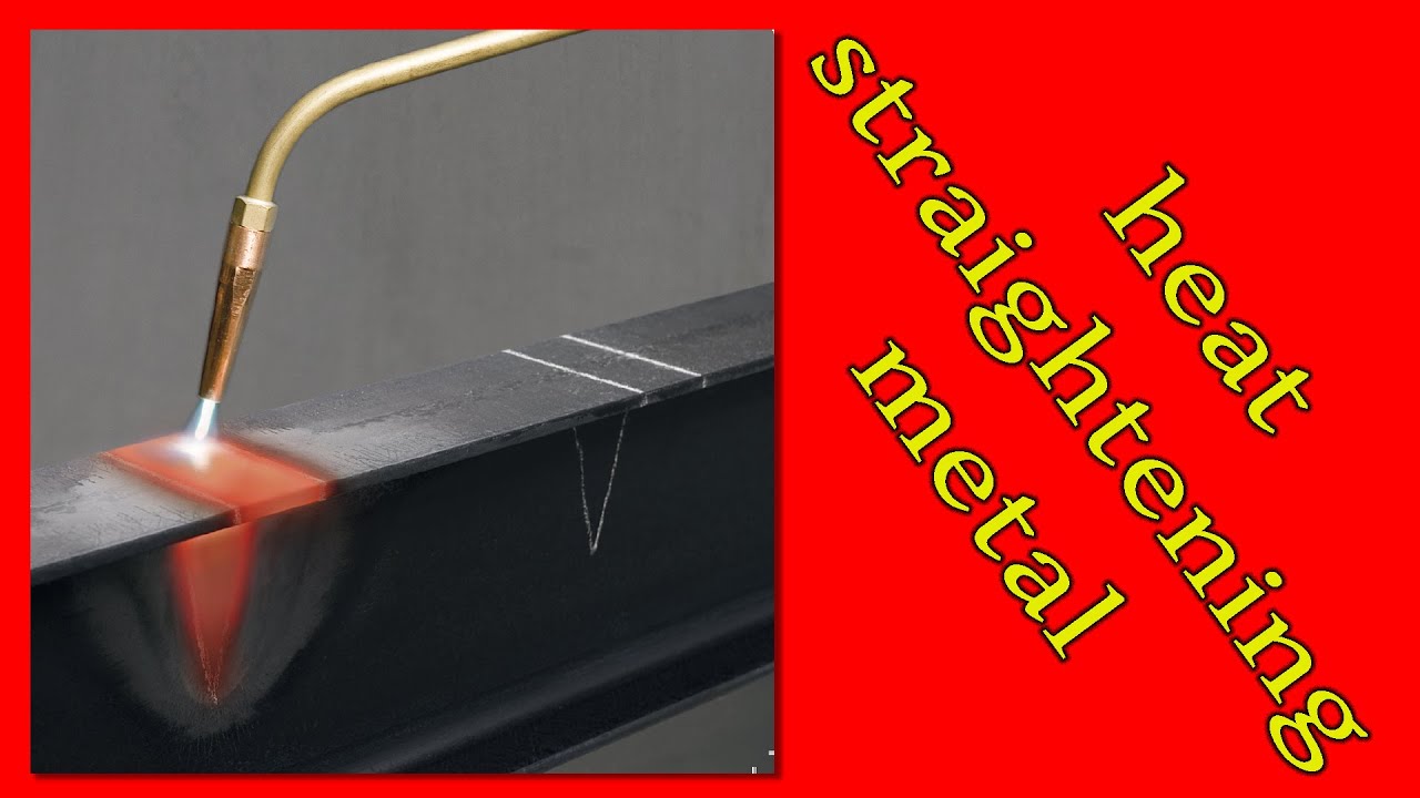
Heat straightening applies controlled heat to deformed areas, using thermal expansion and subsequent natural cooling to guide metal back toward its original configuration. This technique exploits the fundamental behavior of steel: when heated, metal expands, and when that heat is removed through natural cooling, the material contracts. By strategically heating specific zones, you create controlled shrinkage that pulls distorted areas back into alignment. Heat straightening proves particularly suited to heavy sections where mechanical force would be impractical, as the thermal forces generated through heating and cooling exceed what could reasonably be applied through mechanical means.
Strategic Heating Patterns for Maximum Effect
The practical execution requires an oxyacetylene torch or similar heating equipment, with the operator applying measured heat steadily to affected areas while allowing natural cooling to occur. Critical to success is maintaining temperatures below levels that would cause molecular changes in the material structure, typically staying below the point where the metal exhibits cherry-red coloration (approximately 1,400°F). The heating pattern must be carefully planned to create shrinkage in precise locations that will pull the overall structure toward correct alignment, with each heating cycle followed by inspection before proceeding to additional areas.
Key visual cues to watch for:
– When the metal begins to lose its reflective quality (around 900°F), you’ve reached the ideal temperature range for heat straightening
– As the heated area cools, watch for visible movement as the metal contracts
– If blue discoloration appears after cooling, you’ve overheated the area (exceeding 600°F)
For heavy structural sections, use a “V” or “U” shaped heating pattern on the convex side of the distortion. The point of the “V” should face in the direction you want the metal to move. Heat the area to approximately 1,200°F (dull red), then allow to cool naturally without quenching. This creates maximum shrinkage force in the desired direction.
When to Combine Heat and Force for Severe Distortion Correction
Hot mechanical straightening combines thermal and mechanical approaches by heating metal to its yield stress point before applying force to achieve straightening. This hybrid approach allows correction of severe metal distortions that would resist purely mechanical methods while potentially requiring less precise heating control than pure thermal straightening. The elevated temperature reduces the force required to achieve permanent deformation, making it possible to correct distortions in heavier sections that would be impractical to address through mechanical means alone.
Step-by-Step Process for Hot Mechanical Straightening
The process involves heating the affected area to the temperature where material begins to distort plastically (typically 1,200-1,400°F for carbon steel), then applying mechanical force to bend the part toward its intended geometry. At yield stress temperature, relatively small forces produce permanent deformation, allowing the operator to achieve significant correction with controlled application. The combination of heat and mechanical force creates a predictable response that experienced operators can use to achieve precise alignment within the capabilities of the equipment and fixturing available.
Critical safety considerations:
– Always wear full PPE including heat-resistant gloves, face shield, and appropriate clothing
– Ensure adequate ventilation to avoid exposure to fumes
– Keep fire extinguishing equipment nearby
– Never exceed 1,400°F (cherry red) to avoid altering material properties
Pro tip: For heavy sections, heat a narrow band (1-2 inches wide) along the area requiring correction rather than a broad area. Apply force immediately after heating while the metal is at optimal temperature, then allow to cool slowly without quenching to prevent new residual stresses.
Fixing Oil Canning on Thin Automotive Panels Without Creating New Distortion
Oil canning describes a specific distortion pattern common in thin panel fabrication where welded areas flex visibly inward and outward under light pressure. This phenomenon occurs when welding around a panel edge causes that edge to shrink during cooling while the interior material does not shrink proportionally, leaving the central area effectively too large for its constrained perimeter. The result is a panel that can be pushed inward or outward, exhibiting the characteristic flexing motion that gives the condition its name. This distortion type frequently occurs when butt welding repair sections onto thin wheel arches or other automotive body panels.
Heat Gun Shrinking Method for Automotive Panels
For those without access to gas equipment, an electric heat gun provides sufficient heat to tighten metal in affected areas, though the effect is generally less dramatic than torch-based methods. This technique reduces risk of creating additional distortion while providing adequate correction for many automotive panel applications.
Step-by-step heat gun shrinking:
1. Identify the center of the oil canning area (usually the most flexible point)
2. Heat the affected area with the heat gun on high setting, moving in small circles
3. Continue heating until the metal begins to change color (light straw to bronze)
4. Immediately quench the heated spot with cold water from a spray bottle
5. The rapid cooling creates localized shrinkage that pulls the excess metal inward
6. Repeat in adjacent areas if necessary, working from the center outward
Time estimate: 15-30 minutes per affected panel area, depending on size
Difficulty level: Moderate (requires practice to avoid overheating)
Warning: Never apply heat directly to painted surfaces – remove paint first to prevent toxic fumes and achieve better results.
When Cutting Out and Re-Welding Beats Straightening: A Practical Guide
When distortion proves too severe or complex for straightening methods, sectioning and re-welding provides a fundamental approach by removing the affected area and recreating the joint with improved technique. This method involves cutting out the distorted section, restoring proper fit-up between adjacent pieces, and planning a new welding sequence that avoids repeating the original problem. While more labor-intensive than straightening approaches, sectioning addresses the root cause of distortion rather than merely correcting its symptoms, potentially providing more durable results for critical applications.
How to Execute a Successful Section and Re-Weld Process
The sectioning process begins with identifying the boundaries of the affected area, typically extending beyond the visibly distorted zone into sound material on both sides of the problem section. Cutting is accomplished through sawing, plasma cutting, or grinding depending on material thickness and equipment availability, with care taken to produce clean edges that will accept new weld metal without contamination. After cutting, fit-up must be restored to proper alignment, which may require adjustment of adjacent sections or addition of shim material to achieve correct geometry.
Critical steps for successful sectioning:
1. Mark cut lines at least 2 inches beyond visible distortion into sound material
2. Use a cutting method that minimizes heat input to prevent additional distortion
3. After cutting, clean all edges thoroughly to remove oxidation and contaminants
4. Tack weld the new joint in multiple locations before completing the weld
5. Implement improved welding sequence (see prevention section below)
6. Monitor for distortion during welding and pause to allow cooling if necessary
Pro tip: When sectioning complex fabrications, take digital photos from multiple angles before disassembly to ensure proper re-assembly. For critical dimensions, create temporary alignment pins to maintain position during the re-welding process.
8 Proven Techniques to Prevent Weld Distortion Before It Starts
Prevention techniques applied during the original welding process minimize the need for correction and often prove more efficient than reactive approaches. Prevention strategies address the fundamental causes of distortion by controlling heat input, balancing shrinkage forces, and maintaining structural stability throughout the welding process. The most effective prevention programs combine multiple techniques appropriate to the specific fabrication, material, and production requirements.
Strategic Weld Sequencing to Balance Shrinkage Forces
Weld sequencing and bead placement significantly influence distortion development, as welds pull in the direction they are placed and accumulate shrinkage along their length. Running all passes on one side or in one continuous run builds distortion through unbalanced contraction, while alternating sides, staggering welds, and limiting bead size distributes forces more evenly. Breaking long continuous seams into shorter segments prevents accumulation of shrinkage forces along the entire length, reducing bowing and twisting tendencies.
Step-by-step balanced welding sequence:
1. Tack all joints first to maintain alignment
2. Begin welding at the center of the joint and work outward
3. Alternate between opposite sides of the assembly to balance forces
4. For long seams, use a “skip welding” technique – weld 2-3 inch segments with 4-6 inch gaps
5. Complete the gaps in subsequent passes after the initial segments have cooled
6. Always allow adequate cooling time between passes for thin materials
Common mistake: Welding in one continuous pass without allowing cooling time. This creates heat buildup that significantly increases distortion. Instead, use short beads with cooling intervals, especially on thin materials (under 1/4 inch).
Stainless Steel vs. Aluminum: Material-Specific Distortion Correction Methods

Different materials exhibit varying responses to welding heat and require adapted approaches for distortion correction. Carbon steel represents the most straightforward material for both prevention and correction, with well-understood thermal properties and established techniques for addressing distortion. The relatively high thermal conductivity of carbon steel helps distribute heat and reduce peak temperatures, while its ductility accommodates moderate mechanical straightening without risk of cracking. Most general fabrication shops work primarily with carbon steel and have developed extensive experience with its distortion characteristics.
Special Techniques for Stainless Steel Distortion
Stainless steel presents greater challenges due to its lower thermal conductivity, which concentrates heat in the weld zone and creates steeper thermal gradients. The higher coefficient of thermal expansion means stainless steel moves more during heating and cooling cycles, and its tendency to harden in the heat-affected zone makes it more susceptible to cracking during mechanical straightening. Experienced fabricators characterize stainless steel as more prone to warping than aluminum and significantly more difficult to straighten compared to carbon steel.
Stainless steel-specific correction approaches:
– Use lower heat input than with carbon steel (30-40% reduction)
– Implement more frequent tack welds to maintain alignment
– Allow longer cooling periods between passes
– For correction, use lower temperature heat straightening (900-1,100°F)
– Avoid mechanical straightening when material is cold – warm to 300-400°F first
– Consider stress relief at 1,100-1,200°F after correction to prevent future movement
Critical warning: Never quench stainless steel immediately after heating – the rapid cooling can cause cracking in the heat-affected zone. Allow natural cooling or use forced air cooling instead.
Critical Safety Steps When Fixing Weld Distortion with Heat and Force
Distortion correction operations present safety considerations that must be addressed through appropriate procedures, equipment, and training. Thermal straightening and related heat-based methods create burn hazards from hot metal and torch flames, requiring appropriate personal protective equipment including flame-resistant gloves, face protection, and protective clothing. The heated metal retains significant temperature after torch removal, creating burn hazards during handling and measurement operations.
Essential Safety Checklist for Distortion Correction
Before starting any distortion correction work, complete this safety checklist:
– Confirm adequate ventilation, especially when working with stainless steel (hexavalent chromium hazard)
– Verify fire extinguishers are available and charged
– Ensure work area is clear of flammable materials
– Check that all clamps and mechanical equipment are in good condition
– Confirm PPE is appropriate for the task (leather gloves, full-face shield, flame-resistant clothing)
– Establish clear communication protocols if working in teams
Most overlooked hazard: Metal that has been heated retains heat longer than expected. Always assume metal is hot until proven otherwise with a temperature-indicating stick. Allow at least 30 minutes for thick sections to cool after heating before handling without protective gloves.
Emergency procedure: If a part fails catastrophically during mechanical straightening, immediately release all pressure and move to a safe distance. Do not approach until the situation is stabilized. Document the failure for future analysis to prevent recurrence.
Key Takeaways for Successful Distortion Correction
Weld distortion represents an inherent consequence of the thermal cycles that create strong welded joints, but it can be effectively managed through a combination of prevention techniques and correction methods appropriate to your specific situation. Prevention through heat control, balanced sequencing, proper joint design, and adequate restraint addresses the root causes of distortion and minimizes the need for correction. When distortion does occur, mechanical straightening provides rapid correction for moderate cases, while thermal methods address more severe distortions in heavier sections. Sectioning and re-welding offers a fundamental solution when distortion proves too severe or complex for straightening approaches.
For ongoing success, implement these maintenance practices:
– Document welding parameters and distortion outcomes for each job
– Train all welders on balanced sequencing techniques
– Invest in simple measurement tools for in-process distortion monitoring
– Create standard operating procedures for common distortion scenarios
– Schedule regular team discussions to share successful correction techniques
By mastering these techniques, you’ll reduce rework costs, improve quality, and increase customer satisfaction with your welded fabrications. For more advanced applications, consider specialized training in thermal straightening techniques or invest in distortion monitoring equipment for critical production work. Remember that the most successful fabricators don’t just fix distortion—they prevent it from happening in the first place.
Leave a Reply