You’ve just purchased your new welder and are ready to start your first project, but you’re staring at the back panel wondering how to properly connect it to power. Many DIYers and even experienced metalworkers make critical mistakes when hooking up welding equipment, risking electrical damage, poor performance, or even dangerous safety hazards. Properly connecting your welder requires understanding electrical requirements specific to your model, correct circuit specifications, and essential safety precautions. This guide will walk you through every step of safely connecting your welding machine to power sources, whether you’re setting up a 110V unit in your garage or installing a 240V system in your workshop.
Determining Your Welder’s Electrical Requirements

Before touching any wires, you must identify your specific welder’s power needs. Each welding machine has unique electrical requirements printed on its nameplate, typically located on the back or side panel. This information is critical because connecting a welder to an incompatible power source can destroy the machine or create fire hazards.
Reading the Nameplate Specifications
Your welder’s nameplate will display essential information including:
– Input voltage (120V, 240V, or dual voltage)
– Required amperage
– Duty cycle at specific amperages
– Recommended circuit breaker size
– Plug configuration type
For example, a typical MIG welder might require 240V input with a 50-amp circuit, while smaller hobby units often operate on standard 120V household current. Never assume your welder’s requirements based on size or appearance alone—always consult the manufacturer’s specifications.
110V vs 240V Welder Setup Differences
The voltage requirements determine your entire electrical setup approach. 110V welders plug into standard household outlets but are limited to thinner materials, typically up to 1/8 inch steel. These units usually require a dedicated 20-30 amp circuit with 12-gauge or thicker wiring.
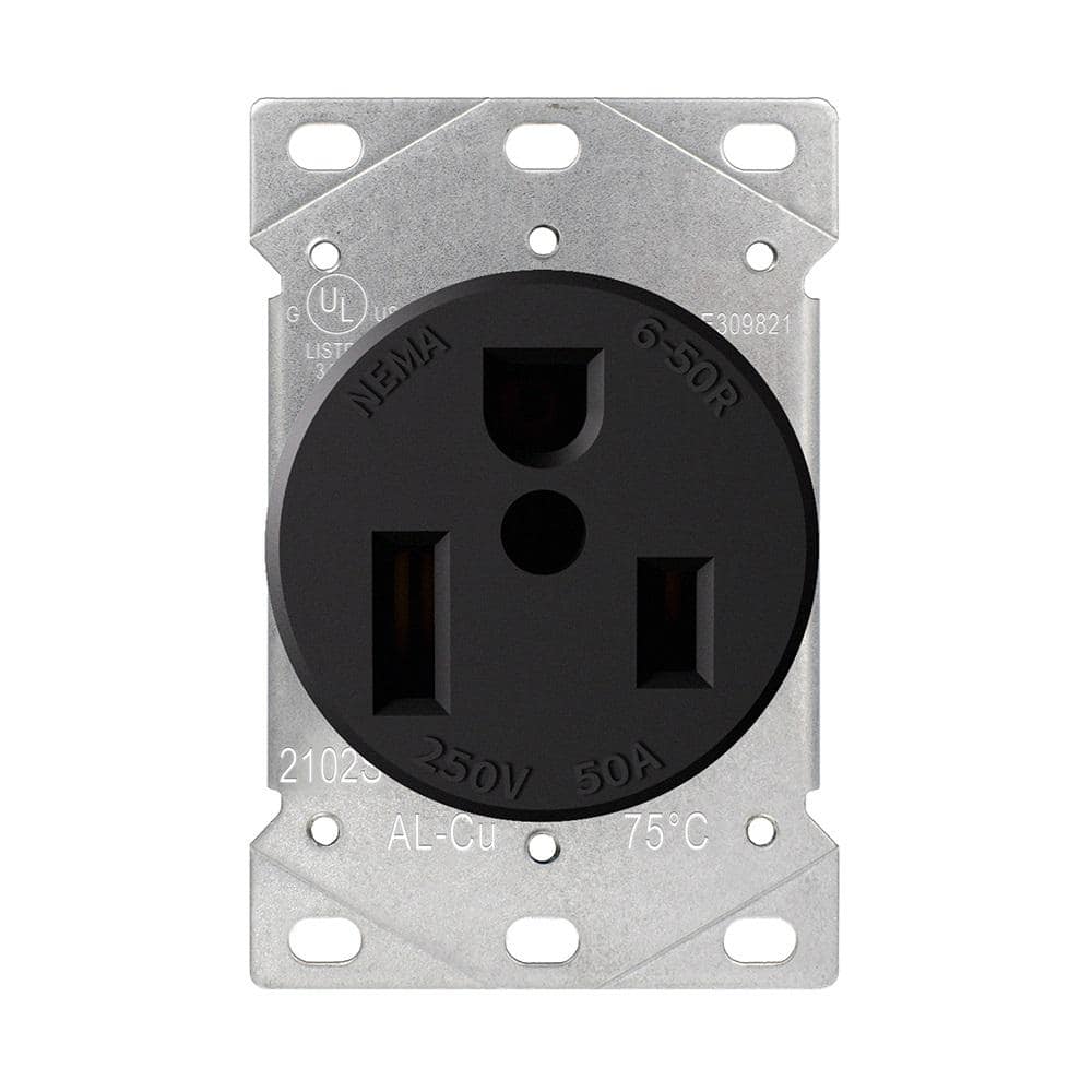
240V welders deliver significantly more power for thicker materials but require specialized electrical infrastructure. These units need either a NEMA 6-50 receptacle (50-amp) or NEMA 14-50 receptacle (50-amp), depending on whether they require a neutral wire. Most professional-grade MIG and TIG welders operate at 240V, while stick welders often support dual voltage configurations.
Circuit Requirements and Electrical Infrastructure

Installing proper electrical infrastructure is non-negotiable for safe welding operations. Many workshop fires originate from improper electrical setups that can’t handle welding equipment demands.
Calculating Correct Circuit Breaker Size
Your circuit breaker must match your welder’s requirements precisely. As a general rule, the breaker size should be 125% of the welder’s maximum input current. For instance, if your welder draws 40 amps at maximum, you’ll need a 50-amp breaker (40 x 1.25 = 50).
Critical mistake to avoid: Never install a larger breaker to prevent tripping—it’s a fire hazard. If your breaker trips during normal operation, you need to address the underlying circuit issue rather than bypassing safety mechanisms.
Selecting Proper Wire Gauge
The wire gauge between your electrical panel and welder receptacle must handle the current without overheating. Common requirements include:
– 120V circuits: 12-gauge wire for 20-amp circuits, 10-gauge for 30-amp
– 240V circuits: 6-gauge wire for 50-amp circuits, 8-gauge for 40-amp
Longer circuit runs require thicker gauges to compensate for voltage drop. For runs exceeding 50 feet, consult NEC (National Electrical Code) tables or an electrician to determine appropriate wire sizing.
Proper Receptacle Installation
Installing the correct receptacle is crucial for safe, reliable operation. Using the wrong outlet type can cause arcing, overheating, or equipment damage.
NEMA Configuration Standards
Welder receptacles follow specific NEMA configurations:
– NEMA 5-20R: Standard 120V, 20-amp household outlet (one vertical slot, one horizontal slot)
– NEMA 6-50R: 240V, 50-amp outlet (two horizontal slots at 90 degrees)
– NEMA 14-50R: 240V/120V, 50-amp outlet (two horizontal slots, one L-shaped slot, one round ground)
Pro tip: Always verify your welder’s plug configuration against the receptacle before installation. Forgetting to check can lead to costly rework when your welder’s plug doesn’t match your newly installed outlet.
Grounding Essentials
Proper grounding is non-negotiable for welding equipment. Your circuit must include an equipment grounding conductor (EGC) connected to the grounding terminal on both the receptacle and your electrical panel. The ground wire should match the size of your current-carrying conductors.
Critical safety point: Never remove the ground pin from a plug or use cheater adapters to force a connection. Welding generates significant electrical noise and potential faults that require proper grounding for safety.
Step-by-Step Welder Connection Process
With your electrical infrastructure properly installed, you’re ready to connect your welder.
Pre-Connection Safety Check
Before plugging in your welder:
1. Verify power is OFF at the circuit breaker
2. Confirm all connections are tight and secure
3. Inspect power cord for damage
4. Ensure work area is dry and well-ventilated
Connecting to Power Source
For 120V units:
1. Plug the welder directly into the dedicated circuit outlet
2. Never use extension cords unless specifically rated for welding
3. Turn on power at breaker and verify welder indicators function
For 240V units:
1. Align plug prongs with receptacle slots
2. Push firmly until fully seated (should require moderate pressure)
3. Secure with retaining screw if your plug has one
4. Restore power at breaker
Testing Initial Operation
After connection:
1. Perform a test run at lowest setting
2. Listen for unusual buzzing or humming
3. Check for excessive heat at plug/receptacle
4. Verify stable arc performance
Warning: If you notice burning smells, excessive heat at connections, or flickering workshop lights, immediately shut off power and recheck your installation.
Extension Cord Guidelines for Portable Welding
When working away from fixed power sources, proper extension cord selection is critical.
Selecting the Right Extension Cord
For welding applications, extension cords must be:
– Rated for the full amperage of your welder
– As short as possible (maximum 50 feet recommended)
– Minimum 10-gauge for 30-amp welders, 8-gauge for 40-50 amp
– Specifically labeled for “industrial” or “welder” use
Common mistake: Using standard household extension cords rated only for 15 amps with welding equipment causes dangerous voltage drop and overheating.
Calculating Voltage Drop
Longer cords increase resistance, reducing voltage at your welder. For 50-foot runs:
– 10-gauge cord: Acceptable for 30-amp, 120V welders
– 8-gauge cord: Required for 40-50 amp, 240V welders
– 6-gauge cord: Necessary for runs exceeding 50 feet
Generator Power Considerations
When working remotely without grid power, generator compatibility becomes essential.
Minimum Generator Size Requirements
Your generator must provide at least 25% more power than your welder’s maximum input requirement. For example:
– 150-amp welder (requiring 30-40 amps input): Minimum 6,000-watt generator
– 200-amp welder: Minimum 8,000-watt generator
Critical specification: The generator must provide “clean power” with less than 5% total harmonic distortion (THD). Inverter generators typically meet this requirement while conventional generators often do not.
Generator Connection Methods
Two safe connection methods:
1. Direct plug: Using appropriate adapter from generator to welder
2. Transfer switch: For permanent generator installations
Never backfeed power into your home’s electrical system without a proper transfer switch—it can electrocute utility workers and damage equipment.
Troubleshooting Common Connection Issues
Even with proper installation, problems can occur. Knowing how to diagnose issues prevents frustration and potential hazards.
Intermittent Power Problems
If your welder cuts out during operation:
– Check for loose connections at receptacle and breaker
– Verify no other high-draw equipment shares the circuit
– Test voltage under load (should stay within 10% of nominal)
Tripping Breakers
Breaker trips indicate overload or fault:
– Ensure you’re not exceeding duty cycle
– Check for short circuits in work cable or electrode holder
– Verify breaker hasn’t degraded from age
Maintenance and Safety Checks
Regular electrical maintenance prevents dangerous situations.
Monthly Safety Inspection
Check:
– Plug and receptacle for signs of arcing or melting
– Power cord for cuts, abrasions, or exposed wires
– Ground connection integrity
– Tightness of all terminal screws
Pro tip: Mark receptacles used for welding with “WELDER ONLY” labels to prevent others from plugging in incompatible equipment.
Seasonal Electrical Review
Before heavy usage periods:
– Clean oxidation from plug contacts
– Tighten connections in electrical panel
– Verify grounding system resistance
– Test GFCI protection if installed
Final Note: Proper welder hookup requires matching electrical infrastructure to your specific machine’s requirements. Never compromise on circuit specifications or safety measures—electrical mistakes with welding equipment can cause equipment damage, poor weld quality, or serious safety hazards. Always consult your welder’s manual for model-specific requirements, and when in doubt, hire a licensed electrician familiar with welding equipment installations. Once properly connected, perform regular maintenance checks to ensure your electrical system continues to support safe, reliable welding operations.
Leave a Reply