Have you ever wanted to create professional-quality welds on aluminum, stainless steel, or exotic metals without spending thousands on commercial equipment? Building your own TIG (Tungsten Inert Gas) welder is an ambitious but achievable project that puts you in complete control of your welding capabilities. With intermediate electronics skills and mechanical aptitude, you can construct a TIG welder that rivals store-bought models at a fraction of the cost. This guide reveals exactly how to make a TIG welder from scratch, addressing the critical components, safety considerations, and assembly techniques that separate successful DIY builds from dangerous failures.
Unlike simpler welding processes, TIG demands precise current control and stable arc performance. Your DIY build must deliver clean, steady power with minimal ripple to maintain that characteristic concentrated arc column. Whether you’re repairing bicycle frames, fabricating custom automotive parts, or working with thin sheet metal, understanding the fundamental requirements before starting your project will determine your success. By the end of this guide, you’ll know exactly what components you need, how to safely assemble them, and how to test your homemade TIG welder for reliable, professional results.
Choosing Between Transformer and Inverter Power Supply Designs
Transformer-Based Welder Construction for Beginners
Transformer designs offer the simplest path for first-time builders despite their significant weight penalty—expect a 50-pound unit versus 15-20 pounds for equivalent inverter models. Start by sourcing an E-I laminated core, preferably from a modified microwave oven transformer (MOT), though remember MOT cores require adaptation for 50/60 Hz mains frequency operation. Wind the secondary coil using 8 to 4 AWG magnet wire in multiple parallel strands to handle 150-200 amps while fitting through the core window. Pack windings tightly and insulate meticulously before impregnating the entire assembly with varnish or epoxy to prevent vibration damage and ensure thermal stability.
Inverter Circuit Assembly for Advanced Builders
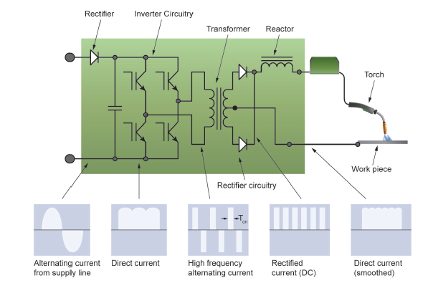
If you have high-voltage electronics experience, the inverter approach delivers superior performance in a compact package. Construct the switching stage using high-power MOSFETs or IGBTs controlled by specialized driver circuits. Design a small high-frequency transformer for isolation and voltage transformation, followed by output rectification and filtering components. Implement feedback control loops for precise current regulation—this is where most DIY inverter projects fail. The complexity demands careful PCB layout and thermal management but enables features like pulse welding and digital displays that transformer designs can’t match.
Building the High-Frequency Arc Start System
Spark Gap Generator Assembly
The high-frequency circuit must generate 2,000-5,000 volts at 1-3 MHz to ionize the gas path between electrode and workpiece. Create a spark gap generator using a simple mechanical or electronic spark gap to produce high-frequency oscillations. Wind the output transformer with ferrite cores and minimal primary turns—high frequency enables efficient energy transfer through weak coupling. Enclose the entire circuit in a grounded metal box to contain electromagnetic interference that could disrupt nearby electronics.
Critical Shielding and Grounding Techniques
Connect shielded cables between the high-frequency generator and torch to prevent radio frequency interference. Ground the work lead directly to the workpiece near the weld area—never rely on the building’s electrical ground. Measure interference levels with a portable AM radio; excessive static indicates inadequate shielding that must be corrected before welding. Verify the HF output can initiate an arc across a 1/4-inch gap but isn’t so strong that it causes equipment malfunctions.
Assembling the Torch System and Gas Delivery
Commercial Torch Integration (Recommended)
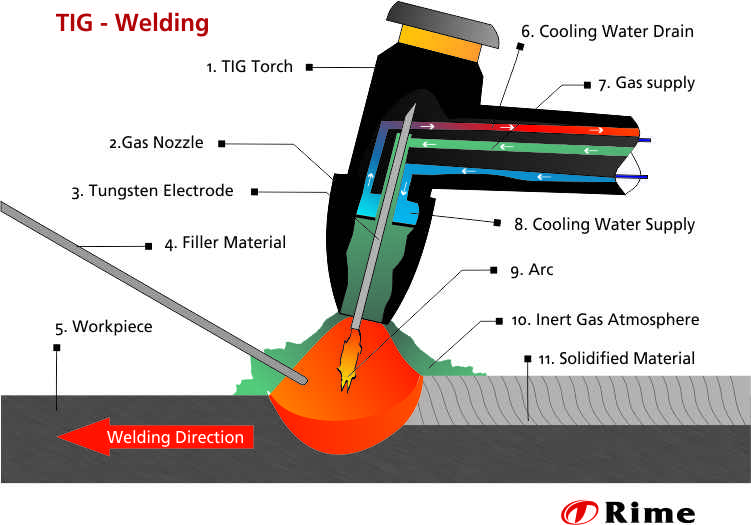
Most successful DIY builders purchase a quality commercial torch rather than fabricating one from scratch—a wise investment of $50-$200 that avoids precision machining challenges. Select a 60-degree head angle for general-purpose work, ensuring the collet size matches your chosen tungsten diameter (1/16″, 3/32″, or 1/8″). Position the electrode to extend from the torch collet by a distance equal to its diameter for optimal gas coverage and arc cone shape. Ceramic gas cups provide adequate protection for most applications while remaining affordable.
Precision Gas Flow Control Setup
Connect your argon cylinder to a dual-stage regulator that reduces 2,000 PSI cylinder pressure to 10-30 PSI working pressure. Install an adjustable needle valve with visual float ball to set flow rates between 15-25 cubic feet per hour—critical for preventing atmospheric contamination. Use high-quality argon-rated gas hose for connections, sealing tapered pipe threads with PTFE tape. Test for leaks using soapy water on all connections while gas flows. Remember: too little flow causes oxidation; too much creates turbulence that also contaminates the weld pool.
Implementing Critical Safety Systems
Electrical Safety Interlocks and Grounding
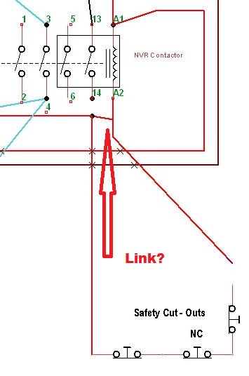
Bond all conductive enclosures to earth ground through the power cord’s ground pin—never skip this life-saving step. Install a thermal cutoff switch on the transformer or inverter heatsink that interrupts power if temperatures exceed safe limits. Add a coolant flow interlock that prevents welding when cooling circulation drops below minimum requirements. Before touching any circuit after operation, discharge capacitors through a proper resistor and verify with a multimeter—inverter designs retain lethal charges long after unplugging.
Personal Protective Equipment Requirements
Never operate your DIY TIG welder without proper protection: a shade 10-12 auto-darkening helmet, leather gloves, long sleeves, and flame-resistant clothing. Set up local exhaust ventilation to remove welding fumes from your breathing zone—especially critical when welding stainless steel or aluminum. Clear all flammable materials from your work area and keep a Class ABC fire extinguisher within arm’s reach. Position yourself so you won’t trip over cables or accidentally contact live components during operation.
Testing and Calibration Procedures
Progressive Power-Up Sequence
Begin testing with all safety interlocks enabled and the torch disconnected. Apply power at minimum current setting while monitoring input current with a clamp meter. Gradually increase current while checking for unusual noises, smells, or excessive heating. Verify the high-frequency circuit produces consistent sparks across a 1/4-inch gap with the torch grounded. Only after confirming stable operation at low power should you attempt actual welding.
Weld Quality Verification on Test Coupons
Start welding on mild steel scrap at the lowest current setting. Evaluate arc stability, bead shape, and penetration depth. Measure actual output current with a calibrated shunt meter to verify control calibration. If the arc sputters or wanders, check for:
– Contaminated tungsten electrode
– Inadequate gas flow rate
– Poor work lead grounding
– High-frequency interference issues
Adjust settings systematically until you achieve consistent, stable arcs with clean bead profiles before attempting critical welds.
Maintenance Protocol for Long-Term Reliability
Monthly Power Supply Inspection
Clean accumulated dust from the power supply interior using compressed air—never a vacuum which can generate static discharge. Check all electrical connections for tightness, as thermal cycling loosens screws over time. Inspect transformer windings and component leads for discoloration indicating overheating. Replace any components showing signs of damage before they cause catastrophic failure.
Torch Consumable Replacement Schedule
Replace the tungsten electrode when it becomes contaminated or develops an irregular tip shape. Inspect the collet for wear that could cause poor electrode grip—replace if it no longer holds tungsten securely. Check gas cups for cracks or heavy spatter buildup that restricts shielding gas flow. Store the torch coiled loosely with no sharp bends to prevent internal wire damage.
Building your own TIG welder delivers immense satisfaction and complete customization but demands respect for electrical hazards and welding physics. By following this systematic construction approach—starting with a transformer design if you’re new to high-power electronics—you’ll create a capable machine that produces professional results on steel, stainless, and aluminum. Remember that patience during construction pays dividends in reliable performance: test each subsystem thoroughly before integration, never compromise on safety systems, and don’t rush to high-power operation before verifying stability at lower settings. With proper maintenance, your DIY TIG welder will serve you for years while giving you the precise control needed for the cleanest possible welds on challenging materials.
Leave a Reply