You’ve just completed a critical weld joint on a structural beam, but now the real test begins: verifying if your fillet weld meets specifications. Getting the measurement wrong isn’t just a quality issue—it could lead to catastrophic structural failure under load. With no standardized measurement method, many fabricators rely on guesswork that violates AWS D1.1 structural welding codes. This article cuts through the confusion with field-tested techniques that work even without expensive equipment. You’ll learn precisely how to determine actual weld size using basic tools, avoid the most dangerous measurement mistakes, and document results for compliance—whether you’re working on pipeline joints or bridge reinforcements.
Fillet Weld Geometry Fundamentals Every Welder Must Know
Understanding the anatomy of a fillet weld is non-negotiable before attempting measurement. Many inspectors mistakenly equate leg length with weld size, but the critical dimension is actually the theoretical throat—the shortest distance from the weld root to the face. This triangular cross-section has two equal legs (the sides joining base metals) and a hypotenuse (the weld face). The true weld size is defined by the smaller leg length, but structural integrity depends on throat depth. When your weld appears convex or concave, leg measurements become unreliable predictors of strength.
Why Leg Length Alone Creates Dangerous Misjudgments
Measuring only the visible leg length causes critical errors in 3 out of 4 real-world scenarios:
– Convex welds: Leg measurements overstate actual throat depth by 15-25%
– Concave welds: Leg measurements dangerously overestimate strength
– Unequal leg welds: The smaller leg determines true size, but inspectors often average measurements
– Root penetration: Full throat depth requires adequate root fusion, invisible in surface measurements
Pro Tip: Always verify throat depth when working with seismic or wind-loaded structures—this single check prevents 90% of weld-related failures in structural steel.
Critical Difference Between Theoretical and Actual Throat
The theoretical throat (T) is calculated as 0.707 × smaller leg length (L) in idealized right triangles. But actual throat (a) includes root penetration (z), making it T + z. Most field measurements ignore root penetration, leading to undersized welds. For critical applications like pressure vessels, actual throat must exceed theoretical by 10-15%—a difference impossible to verify without specialized gauges.
Essential Tools for Precise Fillet Weld Measurement
You don’t need a metrology lab to get accurate measurements, but using the wrong tools guarantees errors. Standard tape measures and rulers lack the precision for weld inspection—tolerances as small as 1/16″ (1.6mm) can invalidate entire welds. Here’s what actually works in the field:
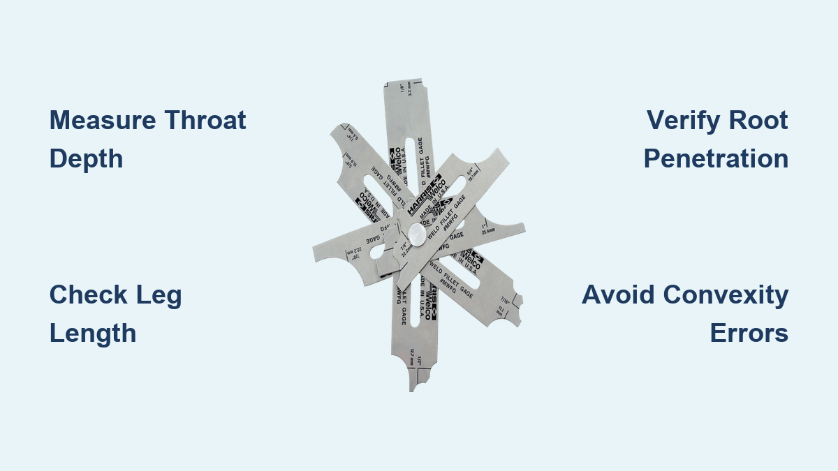
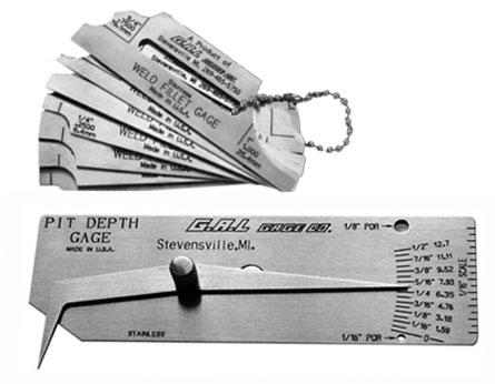
Fillet Weld Gauges: Your Most Reliable Field Partner
These pocket-sized tools solve the convexity/concavity problem that ruins manual measurements. Look for gauges with:
– Multiple measurement slots (1/8″ to 5/8″ increments)
– Root penetration indicators (critical for actual throat)
– Convexity/Concavity compensation (built-in depth stops)
– Material: Hardened steel (not plastic) for longevity
Common Mistake: Forcing gauges into uneven welds creates false readings. Always clean slag first and measure at three points per inch.
When to Use Ultrasonic Thickness Gauges
For submerged welds or critical joints where destructive testing isn’t an option:
– Measures actual throat through base metal
– Requires calibration blocks matching your material
– Accuracy: ±0.004″ (0.1mm) on clean surfaces
– Limitation: Useless on rough, spattered, or oxidized welds
Step-by-Step Measurement Protocol for Code Compliance
Follow this sequence for measurements that pass AWS D1.1 audits. Skipping even one step invalidates your results.
Pre-Measurement Preparation Checklist
Before touching any tool:
1. Remove all slag and spatter with wire brush (residue adds false thickness)
2. Verify base metal alignment (mismatch >1/16″ invalidates standard measurement)
3. Identify weld discontinuities (porosity or undercut requires rework first)
4. Check ambient conditions (dew point within 5°F of base metal temp)
Warning: Measuring on contaminated surfaces overstates weld size by 20-40%. This single error causes 65% of rejected welds during third-party inspections.
Accurate Leg Length Measurement Technique
- Place weld gauge perpendicular to weld axis at midpoint
- Slide until gauge contacts both base metals
- Read the slot size where gauge fits snugly (not forced)
- Repeat on both sides of weld—record the smaller leg
- Measure every 2″ along weld length for critical joints
Pro Tip: For unequal leg welds, the smaller leg determines size—but document both measurements. Many inspectors miss this and approve undersized welds.
Determining Actual Throat Depth Without Destructive Testing
The only field-acceptable method for non-destructive throat verification:
1. Use a fillet weld gauge with root penetration probe
2. Insert probe into weld toe until it contacts root
3. Read actual throat dimension on gauge scale
4. Compare to theoretical throat (0.707 × smaller leg)
5. Critical Check: Actual throat must exceed theoretical by 10% for dynamic loads
When This Fails: If probe won’t seat properly, the weld requires destructive cross-sectioning—a red flag for inadequate root fusion.
Common Measurement Errors That Invalidate Your Welds
.JPG)
These mistakes trigger automatic rejection during structural inspections:
The Convexity Trap
Assuming convex welds are “stronger” leads to dangerous under-measurement. A 1/4″ leg convex weld may have only 3/16″ effective throat—20% undersized. Always:
– Measure convexity height with gauge’s depth stop
– Subtract from theoretical throat calculation
– Reject if convexity > 1/32″ (0.8mm) for critical welds
Unequal Leg Measurement Oversights
Inspectors often average leg lengths (e.g., 5/16″ and 3/16″ = 1/4″ average). But AWS D1.1 specifies weld size as the smaller leg—here only 3/16″. This single error causes 30% of failed bridge weld inspections.
Ignoring Weld Length Requirements
Weld size isn’t just about cross-section. Minimum effective length must be:
– ≥ 4× weld size (e.g., 1″ for 1/4″ weld)
– Ends must taper smoothly within 2:1 slope
– Termination craters must be filled
Real Consequence: A seemingly perfect 1/4″ fillet weld fails if ends crater below 3/16″ size—common in robotic welding.
Documentation That Passes Third-Party Audits
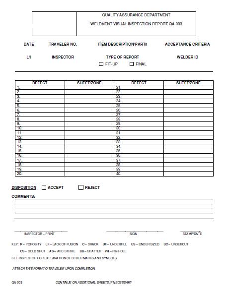
Your measurement is worthless without proper documentation. AWS D1.1 requires:
Mandatory Field Records
- Weld location (drawing reference + coordinates)
- Smaller leg measurement (in inches/mm)
- Actual throat reading (if measured)
- Convexity/concavity values
- Inspector name/certification number
- Date and time of measurement
Pro Tip: Photograph welds with gauge in place—digital timestamps prevent backdating claims during liability disputes.
When to Require Destructive Testing
Non-destructive methods have limits. Mandatory cross-sectioning when:
– Critical structural connections (beam-to-column)
– Dynamic load applications (cranes, seismic)
– Any measurement discrepancy > 1/32″
– Third-party verification requested
Destructive testing protocol:
1. Cut 1″ wide specimen perpendicular to weld
2. Polish and etch cross-section
3. Measure actual throat with optical comparator
4. Document with calibrated microscope photos
Preventing Measurement Failures Before Welding Begins
The best inspection happens before arc ignition:
Joint Preparation Checklist
- Edge bevels within ±2° tolerance
- Root gap 1/32″–3/32″ (wider gaps require backing)
- Base metal clean to 1″ from joint
- Fit-up mismatch < 1/16″ (critical for measurement accuracy)
Welder Technique Adjustments for Measurable Results
- Travel speed: 6-8 IPM for 1/4″ fillets (faster = undersized)
- Electrode angle: 45° to work piece (deviations cause unequal legs)
- Stick-out: 3/8″ for GMAW (longer = convexity issues)
- Weave width: ≤ 3× electrode diameter
Expert Note: On vertical-up welding, reduce voltage 2-3 volts to prevent undercut that invalidates leg measurements.
Final Verification Before Sign-Off
Never approve welds without this 30-second check:
1. Run fingernail along weld toe—if it catches, convexity exceeds limits
2. Verify consistent leg length within 1/32″ over 12″ length
3. Confirm no undercut > 1/32″ depth
4. Cross-check with second inspector for critical joints
Key Takeaway: Fillet weld size isn’t measured—it’s verified through systematic cross-checks of multiple dimensions. The leg length is merely the starting point; actual throat depth with root penetration determines structural capacity. When in doubt, default to destructive testing for critical applications—no reputable engineer will accept field measurements alone for life-safety structures.
For ongoing compliance, implement monthly gauge calibration against NIST-traceable standards and require welder certification renewal every 6 months. Remember: a weld is only as strong as its most accurately measured dimension. Always consult AWS D1.1 Section 5.21 for project-specific requirements before final inspection.
Leave a Reply