Welding cracks represent one of the most serious defects in metal fabrication, compromising structural integrity and potentially leading to catastrophic failures. When your carefully crafted weld develops cracks, it’s not just a cosmetic issue—it’s a critical weakness that could cause your entire project to fail under stress. Understanding how to prevent crack in welding is essential knowledge for both professional welders and serious DIY enthusiasts who demand reliable, long-lasting results. This guide cuts through the confusion by delivering actionable, field-tested strategies that address the root causes of welding cracks rather than just treating symptoms. You’ll discover specific temperature ranges, material preparation techniques, and process adjustments that eliminate cracks before they start—saving you time, materials, and potentially dangerous situations down the line.
Why Your Welds Develop Cracks and How to Stop Them Immediately

Welding cracks primarily form due to three factors: residual stresses exceeding the metal’s strength, improper cooling rates, and hydrogen embrittlement in susceptible materials. Hot cracks appear while the weld is still cooling and molten, typically along the centerline of the bead, while cold cracks develop hours or even days after welding when hydrogen has migrated to stress points. The most effective prevention strategy begins with identifying which type of crack you’re dealing with, as each requires different corrective actions. For immediate crack prevention, maintain your interpass temperature between 500-1,100°F depending on material thickness—this critical range prevents the thermal shock that causes most hot cracking issues.
Identifying Hot Cracks vs. Cold Cracks in Your Welds
Hot cracks form at high temperatures during solidification and appear as jagged, irregular lines following the weld bead’s direction. They’re most common in high-sulfur steels and aluminum alloys. Cold cracks, however, create straight, clean fractures that often penetrate through the weld and into the base metal, typically appearing 24-48 hours after welding. The key visual difference: hot cracks have oxidized surfaces from high-temperature exposure, while cold cracks show fresh metal. If you spot cracks immediately after welding, focus on adjusting your travel speed and heat input; if they appear later, prioritize hydrogen control and post-weld heat treatment.
The Temperature Threshold That Causes Most Weld Failures
Exceeding 1,200°F during the cooling phase creates the perfect conditions for hot cracking in most carbon steels. Use an infrared thermometer to monitor your weld zone and maintain a consistent cooling rate below 150°F per minute for metals thicker than 1/4 inch. For critical applications, invest in a thermal crayon set that melts at specific temperatures—these provide instant visual feedback when your base metal reaches dangerous thresholds. Never allow your weld to cool faster than 300°F per minute from 1,000°F to 700°F, as this rapid transition creates internal stresses that exceed the metal’s yield strength.
Proper Metal Preparation: The First Critical Step to Crack Prevention
Contaminated base metals account for over 60% of preventable welding cracks. Oil, paint, moisture, and rust create gas pockets that become stress concentrators as the weld solidifies. The most effective preparation method combines mechanical cleaning with chemical treatment for maximum adhesion and purity.
How to Clean Base Metals for Maximum Crack Resistance
Begin with a stainless steel wire brush dedicated solely to your base metal (never use the same brush on multiple metals). Follow with acetone cleaning to remove invisible oils, then immediately apply a light coat of anti-spatter compound before welding. For critical applications, use a 3M Scotch-Brite pad with 80-120 grit to create a uniform surface profile that improves weld bead wetting. Always clean at least 1 inch beyond the intended weld zone in both directions—residual contaminants outside the immediate area can still migrate into your weld pool during heating.
The Right Way to Remove Moisture Before Welding
Moisture converts to hydrogen during welding, causing delayed cracking in susceptible materials. For outdoor work, preheat metal to 250°F for 30 minutes before welding to drive off surface moisture. When working with pipe or enclosed sections, place silica gel packets inside overnight to absorb trapped humidity. Never rely solely on visual inspection—use a moisture meter to verify surface moisture content below 3% before striking an arc. In high-humidity environments, store electrodes in a heated cabinet at 250-300°F until immediately before use.
Choosing the Perfect Welding Rod for Crack-Free Results
The wrong filler metal can introduce elements that promote cracking or create incompatible thermal expansion characteristics with your base metal. Low-hydrogen electrodes aren’t just recommended for high-strength steels—they’re essential for preventing delayed cracking in any application where structural integrity matters.
Low-Hydrogen Electrodes: Your Best Defense Against Cold Cracks
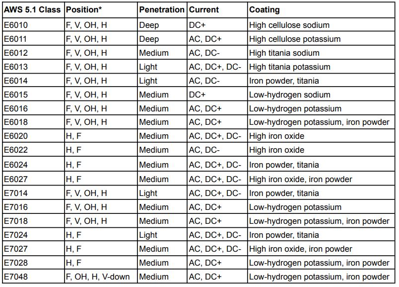
E7018 rods contain a lime-based flux that scavenges hydrogen from the weld pool, reducing hydrogen content to safe levels below 5 ml/100g of weld metal. For critical applications, upgrade to E7018-1 H4R rods with certified maximum hydrogen levels of 4 ml/100g. Always bake low-hydrogen electrodes at 700°F for 2 hours before first use, then store them in a heated holder maintaining 250-300°F between uses. Discard any unused electrodes after 4 hours outside the holder—re-baking won’t restore their low-hydrogen properties.
Matching Filler Metal to Base Metal to Prevent Stress Cracking
Mismatched expansion coefficients cause residual stresses that lead to cracking. When welding dissimilar metals, select filler metals with thermal expansion rates midway between the two base materials. For high-carbon steels, use nickel-based fillers like ENiCrFe-3 that accommodate differential contraction without cracking. Never use higher-strength filler than necessary—excess strength creates brittle zones prone to cracking under stress. Consult AWS A5.1 specifications to match tensile strength within 10% of your base metal for optimal crack resistance.
Optimal Welding Parameters to Eliminate Cracks Before They Start
Most welders focus exclusively on amperage while ignoring equally critical factors like travel speed and arc length. The ideal parameter combination creates sufficient heat for proper fusion without overheating the material or creating excessive residual stresses.
The Precise Amperage Range That Prevents Hot Cracking
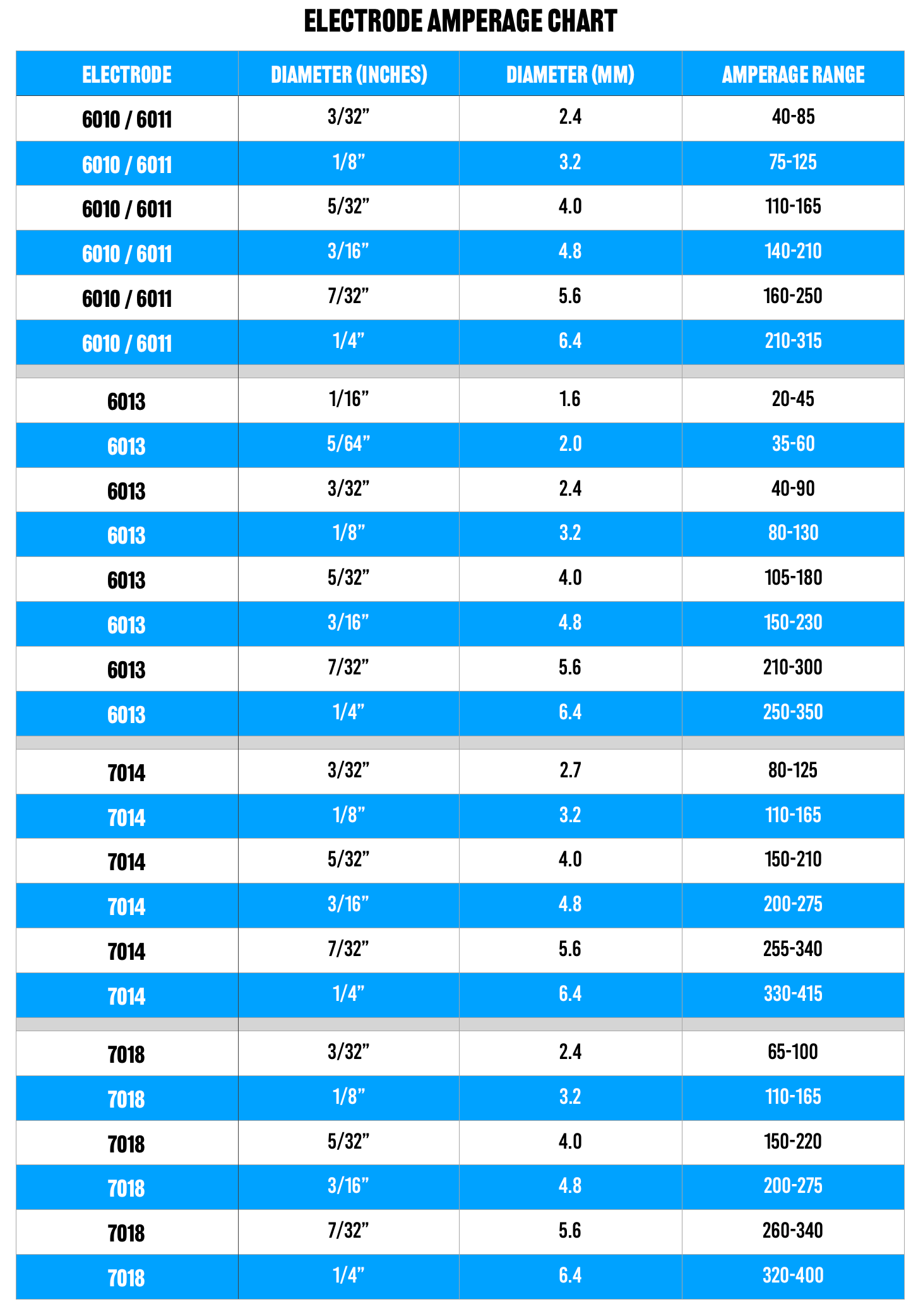
For 1/8-inch E7018 rods on 1/4-inch steel, maintain 110-130 amps; exceeding 140 amps creates wide, shallow penetration that concentrates stresses at the weld toe. Use the “1 amp per 0.001 inch of electrode diameter” rule as your starting point, then adjust based on visual feedback: a properly set amperage creates a quiet, steady arc with minimal spatter and consistent ripples. When welding thin materials, reduce amperage by 15-20% and increase travel speed to prevent burn-through that leads to crater cracks.
Travel Speed Secrets for Stress-Free Welding
Moving too slowly creates wide, convex beads that concentrate stresses at the toes, while excessive speed produces narrow, concave beads prone to centerline cracking. The ideal travel speed creates uniform, slightly convex beads with ripple spacing equal to the electrode diameter. For 1/8-inch electrodes, maintain 6-8 inches per minute on flat positions. Use a consistent wrist motion—never stop moving—and finish each pass with a slight back-and-fill technique to eliminate crater cracks. When welding in vertical positions, increase travel speed by 20% to compensate for natural weld pool sag.
Mastering Preheating Techniques to Prevent Thermal Shock Cracks
Insufficient preheating causes rapid cooling that exceeds critical cooling rates, while excessive preheating wastes energy and can alter material properties. The right preheat temperature depends on material thickness, carbon content, and joint restraint.
Calculating the Exact Preheat Temperature for Your Metal
Use the formula: Preheat (°F) = 1,000 × √(CE) × √(thickness in inches), where CE is the carbon equivalent value from your material certificate. For unknown materials, use these safe baselines: 250°F for 1/2-inch mild steel, 400°F for 1-inch, and 600°F for alloy steels. Always measure preheat temperature 1 inch from the joint on both sides using a calibrated contact thermometer—not an infrared gun, which reads surface temperature only.
How Long to Maintain Preheat for Different Thicknesses
Thin materials (<1/4 inch) require only 5 minutes of preheating, while thick sections (1 inch+) need 30-60 minutes to achieve thermal equilibrium. Continue applying heat until the entire joint area maintains temperature within 50°F of your target during welding. For multi-pass welds, never let interpass temperature drop below your preheat temperature—use thermal blankets between passes on thick sections. Critical applications require continuous temperature monitoring with thermocouples attached directly to the workpiece.
Common Welding Mistakes That Lead to Cracks (And How to Fix Them)
Even experienced welders make preventable errors that create crack-prone welds. Recognizing these patterns early can save hours of rework and potential safety hazards.
The Speed Mistake 90% of Beginners Make
Rushing through welds creates inconsistent heat input that leads to micro-cracks invisible to the naked eye. Professional welders maintain a steady 6-8 inches per minute travel speed regardless of position—use a stopwatch and practice on scrap metal until you develop muscle memory. When welding overhead, reduce your speed by 15% but increase your amperage by 10% to maintain proper penetration without excessive heat buildup.
Why Rushing Between Weld Passes Causes Hidden Cracks
Skipping proper interpass cleaning allows slag inclusions that become crack initiation points. Always wire brush between passes and verify temperature before continuing—too hot causes burn-through, too cold creates cold laps. For critical welds, implement a 5-minute minimum cooling period between passes on thick materials to allow hydrogen diffusion. Never apply subsequent passes while the previous layer is still glowing orange—wait until it cools to 300-400°F for optimal results.
Essential Post-Weld Inspection to Catch Potential Cracks Early
Many cracks develop hours after welding when hydrogen has migrated to stress points. Implementing a structured inspection protocol catches problems before they compromise your entire project.
Visual Inspection Techniques That Reveal Micro-Cracks
Examine welds under 10x magnification 24-48 hours after completion—this is when hydrogen-induced cracks typically appear. Look for hairline fractures at weld toes and crater areas, which indicate stress concentration points. Use a black light with fluorescent penetrant for critical applications; even 0.001-inch cracks become visible under UV light. Any crack longer than 1/8 inch requires complete removal and rewelding—partial repairs never fully eliminate the stress concentration.
Non-Destructive Testing Methods for Critical Welds
For structural applications, implement magnetic particle inspection (MPI) on ferrous metals within 48 hours of welding to detect subsurface cracks. Ultrasonic testing provides depth measurement of detected flaws, while radiographic testing verifies internal integrity without damaging the weld. Establish a pass/fail criterion based on AWS D1.1 standards: no cracks are acceptable in critical load-bearing welds, while non-critical applications may allow isolated micro-cracks under 0.01 inches if they don’t connect.
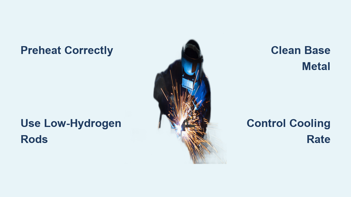
Preventing cracks in welding requires systematic attention to material preparation, process control, and post-weld procedures. By implementing these specific techniques—particularly maintaining precise temperature control, using low-hydrogen consumables properly, and following correct preheat protocols—you’ll dramatically reduce crack formation in your welds. Remember that crack prevention starts long before you strike an arc: proper joint design, material selection, and environmental control contribute significantly to crack-resistant welds. For ongoing success, document your parameters for each successful weld and maintain that recipe for similar future projects—consistency is your strongest defense against welding cracks.
Leave a Reply