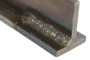
Pinholes in welds can undermine the structural integrity of your work, create leak paths in pressure vessels, and lead to costly rework. These tiny gas pockets form when contaminants interfere with the welding process or when shielding gas doesn’t properly protect the molten pool. If you’ve ever finished a weld only to discover dozens of pinprick holes marring your work, you know the frustration of having to grind down and restart the entire joint. In this guide, you’ll learn proven techniques to eliminate pinholes before they form, saving you time, materials, and headaches on your next welding project.
When pinholes appear in your welds, they’re not just cosmetic flaws—they’re indicators of problems in your process that could compromise the entire structure. Whether you’re fabricating a custom exhaust system, repairing agricultural equipment, or building precision components, preventing these defects starts with understanding their root causes. By the end of this article, you’ll have actionable strategies to identify contamination sources, optimize your technique, and consistently produce clean, pinhole-free welds regardless of material or position.
Identifying Common Causes of Welding Pinholes
Contamination on Base Metal or Filler Material
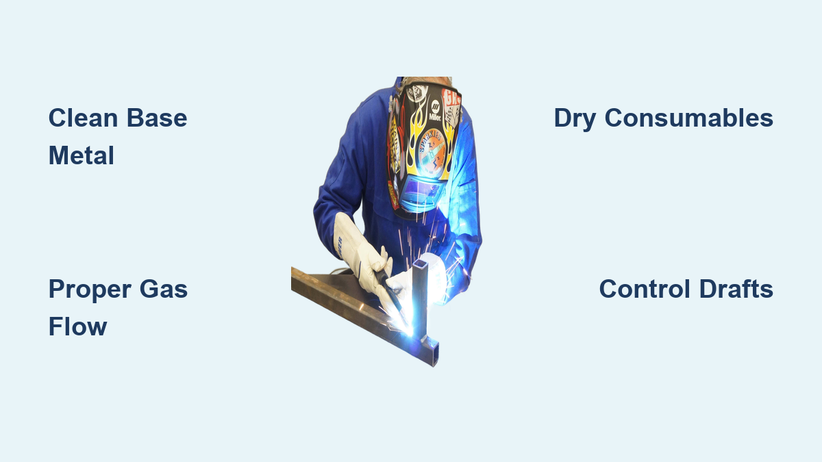
Surface contaminants remain the leading cause of pinholes in welded joints. Oil, grease, moisture, paint, or even fingerprint residue vaporize when exposed to welding temperatures, creating gas pockets that become trapped as the weld solidifies. Metals like aluminum and stainless steel are particularly vulnerable as they readily absorb atmospheric gases when heated. Before striking an arc, thoroughly clean both sides of the joint using a stainless steel wire brush dedicated to that specific metal type—never use the same brush on different metals to avoid cross-contamination. For critical applications, follow brushing with a solvent wipe using acetone or isopropyl alcohol on a clean lint-free cloth.
Inadequate Shielding Gas Coverage
Improper gas flow rates or compromised shielding gas coverage allows atmospheric gases to interact with the molten weld pool. Too little flow (typically below 15 CFH for most applications) fails to displace oxygen and nitrogen, while excessive flow (above 25 CFH) creates turbulence that actually draws in contaminants. Check for gas leaks at all connection points using a commercial leak detection solution, and replace any damaged gas diffusers or nozzles showing signs of spatter buildup. When welding outdoors or in drafty environments, create windbreaks or adjust your position to maintain consistent gas coverage over the weld pool.
Optimizing Your Welding Setup for Pinhole Prevention
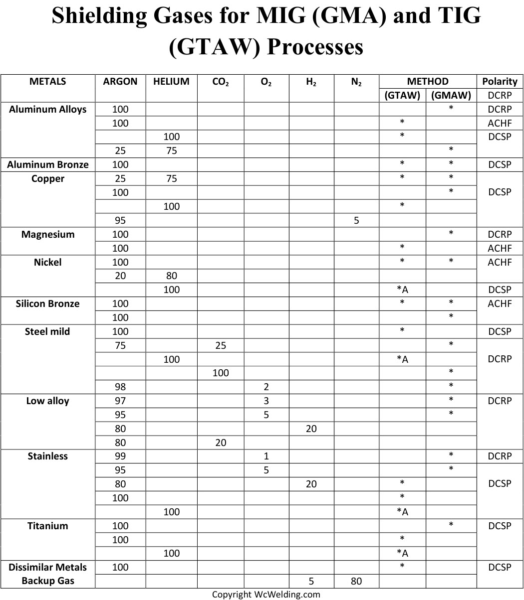
Selecting the Right Shielding Gas Mixture
Different materials require specific gas blends to prevent porosity. For carbon steel, 75% argon/25% CO2 provides excellent arc stability and penetration while minimizing pinholes. Aluminum welding demands pure argon with flow rates adjusted for the joint configuration—typically 20-30 CFH. When working with stainless steel, consider tri-mix gases (90% helium, 7.5% argon, 2.5% CO2) for deeper penetration and cleaner welds on thicker materials. Always verify your gas cylinder has sufficient pressure (minimum 200 PSI remaining) as depleted tanks can introduce moisture into the system.
Proper Electrode and Filler Metal Selection
Moisture-contaminated electrodes cause immediate porosity issues, especially with stick welding processes. Store low-hydrogen rods in a heated holding oven maintained between 250-300°F when not in use, and limit exposure to ambient air to no more than four hours. For MIG welding, use filler metals with proper deoxidizers like silicon and manganese that help counteract oxygen contamination. When switching between materials, dedicate separate spools of wire to prevent cross-contamination that could introduce elements causing pinholes.
Mastering Technique to Eliminate Welding Defects
Maintaining Correct Travel Speed and Angle
Excessive travel speed prevents proper gas coverage and creates insufficient heat input, causing the weld pool to solidify too quickly and trap gases. Conversely, moving too slowly allows more time for atmospheric contamination. Maintain a consistent travel speed that keeps the weld pool slightly ahead of the leading edge of solidification. For MIG welding, use a push technique with a 10-15 degree travel angle to maximize gas coverage; for TIG, maintain a consistent arc length no greater than the electrode diameter. Practice on scrap material until you achieve a uniform, slightly convex bead profile without irregular surface texture.
Proper Joint Preparation and Fit-Up
Poor joint fit-up creates gaps where shielding gas escapes and contaminants enter during welding. Ensure proper root gaps according to material thickness—typically 1/8 inch for 1/4 inch steel. Bevel edges properly for thicker materials to allow complete penetration without excessive heat input. Clamp workpieces securely to prevent movement during welding that could disturb gas coverage. For critical applications, consider back-purging the inside of pipes or tubes with additional argon to prevent oxidation on the root pass.
Environmental Factors That Contribute to Pinhole Formation

Managing Humidity and Temperature Conditions
High humidity introduces moisture that decomposes into hydrogen at welding temperatures, creating pinholes as the gas escapes. Avoid welding outdoors when relative humidity exceeds 60%, or implement environmental controls in your workspace. If working in cold conditions, preheat materials to at least 40°F to prevent condensation on the workpiece. Store welding consumables in climate-controlled environments, as moisture absorption in filler metals directly contributes to porosity issues.
Addressing Drafts and Air Movement
Even subtle air currents can disrupt shielding gas coverage. Position yourself to block natural drafts when possible, and avoid welding near open doors, windows, or ventilation systems. For outdoor work, construct temporary wind barriers using welding curtains or plywood sheets positioned strategically around your work area. When welding in confined spaces, ensure adequate ventilation without creating direct airflow across the weld zone.
Troubleshooting Existing Pinhole Issues
Diagnosing the Source of Porosity
When pinholes appear in your welds, systematically eliminate potential causes starting with the most common. First verify base metal cleanliness by wiping with acetone—if residue appears on the cloth, contamination is likely the culprit. Check gas flow rates with a flowmeter rather than relying on the regulator gauge. Inspect consumables for damage or excessive spatter buildup that restricts gas flow. If problems persist, test with a different cylinder of gas to rule out contaminated supply.
Corrective Actions for Specific Pinhole Patterns
Different pinhole patterns indicate specific problems. Random surface porosity typically indicates general contamination, while linear porosity along the weld centerline suggests inadequate shielding gas. Pinholes concentrated at the start of the weld often mean insufficient gas pre-flow time, while those at the end indicate inadequate post-flow. Adjust your machine settings accordingly—most modern welders allow separate pre-flow (0.5-1 second) and post-flow (5-10 seconds) timing controls to ensure complete gas coverage throughout the welding cycle.
Essential Maintenance Practices for Consistent Results
Regular Equipment Checks and Calibration
Schedule weekly inspections of your welding system to prevent issues before they occur. Check all gas connections for leaks, replace worn contact tips that cause erratic wire feeding, and clean diffusers to maintain proper gas flow patterns. Calibrate voltage and wire feed speed settings according to manufacturer specifications, as improper parameters contribute to unstable arcs and porosity. Keep a maintenance log tracking consumable replacements and system checks to identify patterns before problems develop.
Proper Storage of Consumables
Moisture control extends beyond just electrodes—proper storage of all consumables prevents contamination. Keep filler metals in sealed containers with desiccant packs when not in use, and avoid storing near cleaning solvents or other chemicals that could off-gas contaminants. For flux-cored wires, use only the amount needed for a single shift and reseal the container immediately after use. Label all containers with opening dates and discard materials showing signs of corrosion or discoloration.
Preventing pinholes in welding requires systematic attention to cleanliness, proper setup, and consistent technique. By addressing contamination sources, optimizing your shielding gas coverage, and maintaining your equipment properly, you’ll significantly reduce porosity issues in your welds. Remember that even small improvements in preparation and process control yield dramatic results in weld quality. Implement these strategies during your next project, and you’ll spend less time grinding out defective welds and more time producing strong, reliable joints that meet even the most stringent quality standards. For ongoing improvement, consider keeping a welding log that tracks variables like humidity, gas flow rates, and resulting weld quality to identify patterns specific to your working environment.
Leave a Reply