That ominous silence when you flip the power switch on your welding machine only to be met with complete darkness is enough to halt any project dead in its tracks. Whether you’re in the middle of a critical job or just starting your day, a welding machine with no power presents an immediate roadblock that needs urgent attention. This frustrating issue could stem from something as straightforward as a tripped breaker or as complex as a failed internal component, but knowing how to methodically diagnose and address the problem can save you costly service calls and downtime. In this guide, you’ll learn the exact steps to troubleshoot and repair your powerless welding machine, from basic electrical checks to advanced component testing—getting you back to welding safely and efficiently.
Verify Electrical Supply and Circuit Breaker Status
Before diving into your welding machine’s internals, confirm the problem isn’t with your electrical source. Plug a working device like a shop light or radio into the same outlet to verify power availability. If that device doesn’t work, check your circuit breaker panel for a tripped switch—welding machines frequently trip breakers due to their high amperage draw. Locate the breaker labeled for your welding circuit and firmly flip it to the OFF position before resetting it to ON. For older installations using fuses, inspect the glass element for darkness or a broken filament indicating a blown fuse that needs replacement with an identical amperage rating.
If you’re using an extension cord, ensure it’s heavy-duty with sufficient gauge for your machine’s requirements—undersized cords cause voltage drop that prevents proper operation. Measure voltage at the outlet with a multimeter; you should see 110-120V for standard machines or 220-240V for larger units. Voltage below 105V or above 125V (for 120V circuits) indicates a supply issue that needs correction before proceeding. Remember that shared circuits with other high-draw tools like air compressors or saws often cause intermittent power failures when multiple tools run simultaneously.
Inspect Power Cord and Plug for Physical Damage

Damaged power cords represent one of the most common causes of welding machine power failures. Conduct a thorough inspection of the entire cord length, paying special attention to connection points where stress fractures commonly occur. Feel along the cord for soft spots or internal breaks that might not be visible externally. Look for cuts, abrasions, or melted insulation that could expose conductors and create dangerous shock hazards.
Examine the plug prongs for signs of arcing, melting, or corrosion that would prevent proper electrical contact. For three-prong grounded plugs, ensure the grounding pin is intact and properly seated in the outlet. Check twist-lock connectors for debris in the contact points or damage to the locking mechanism. If you discover any cord damage, replacement is mandatory—never attempt field repairs with electrical tape as this creates fire and shock risks. When installing a new cord, ensure proper strain relief and secure termination to prevent future failures at connection points.
Test and Replace Internal Fuses
Many welding machines incorporate internal fuses that protect sensitive components from power surges. After ensuring the machine is unplugged and capacitors have discharged (wait at least 30 minutes), remove the access panel to locate these fuses near the primary power input. Automotive-style blade fuses or ceramic cartridge fuses are common—inspect them for visible damage like darkened glass or broken filaments.
Critical safety note: Never bypass a blown fuse with wire or foil as this creates serious fire hazards. Replace blown fuses only with identical specifications—using a higher amperage fuse risks catastrophic component failure. If the new fuse blows immediately upon power-up, an underlying short circuit exists that requires further diagnosis before attempting additional repairs. Some machines use resettable circuit breakers instead of fuses; these typically appear as small buttons that pop out when tripped. Press firmly to reset, but investigate the cause of repeated tripping before continuing operation.
Diagnose Power Switch Failure with Multimeter Testing
A faulty power switch often prevents electricity from reaching internal components despite other systems functioning correctly. Using a multimeter set to continuity or resistance mode, test the switch with the machine unplugged. Disconnect wires from the switch terminals and place one probe on each terminal. With the switch OFF, you should measure infinite resistance; with the switch ON, resistance should drop to near zero. No continuity in the ON position indicates switch failure requiring replacement.
When replacing the switch, match the exact specifications including voltage rating, current capacity, and physical dimensions. Document wire positions with photos before disconnection to ensure proper reinstallation. For machines with electronic control panels instead of mechanical switches, power issues may stem from failed display boards or control modules that require more advanced diagnostics and potentially professional repair.
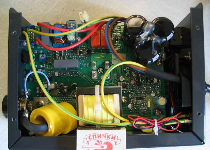
Check Internal Wiring Connections for Loose or Corroded Terminals
Vibration during transport and operation frequently loosens critical electrical connections inside welding machines. With the access panel removed, systematically inspect all terminal connections looking for wires pulled loose, corroded contacts, or burnt insulation indicating arcing. Pay special attention to connections at the transformer input, circuit board interfaces, and fan motor terminals.
Clean corroded terminals with electrical contact cleaner and a small wire brush, then apply dielectric grease to prevent future corrosion. Tighten loose connections to manufacturer specifications—over-tightening can strip threads while under-tightening allows connections to loosen again during use. Replace any wires showing signs of melting or insulation breakdown, ensuring proper gauge and insulation type for welding machine environments. Document your disassembly process with photos to guarantee correct reassembly.
Test Primary Side Transformer Functionality
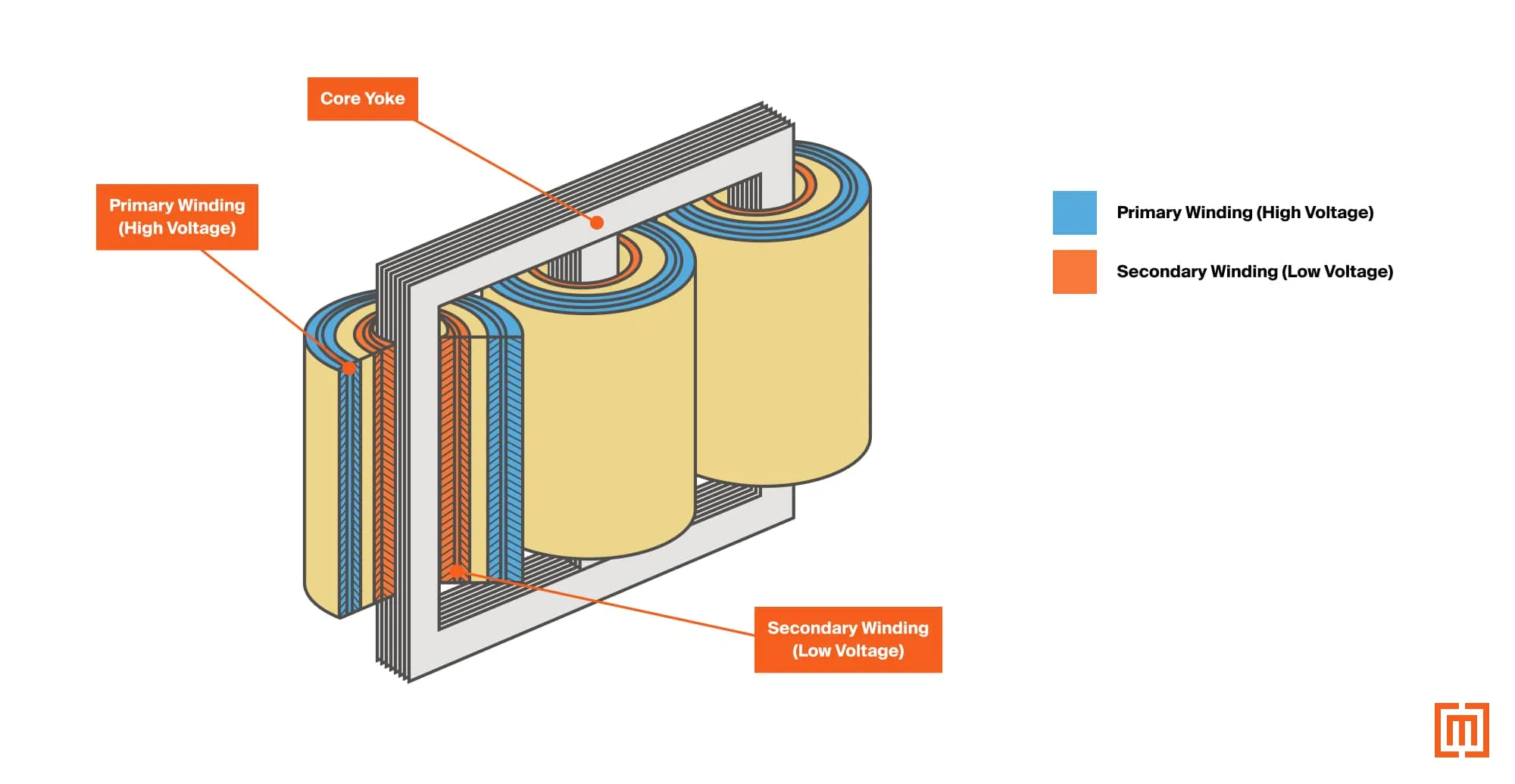
The transformer serves as your welding machine’s power conversion heart, and primary side failures prevent electricity from reaching welding circuits. Using a multimeter set to AC voltage, carefully test for input voltage at the transformer primary terminals while the machine is powered on (exercise extreme caution with live circuits). No voltage here indicates problems in the wiring, switch, or fuse circuit upstream.
If voltage reaches the primary side but the machine remains dead, test the primary winding resistance with your multimeter set to ohms. An open winding (infinite resistance) or shorted winding (very low resistance) confirms transformer failure requiring replacement. Transformer replacement involves precise mounting and secure electrical connections—improper installation creates serious shock hazards and should only be attempted by those experienced with high-voltage equipment.
Inspect Printed Circuit Boards for Failed Components
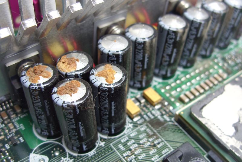
Modern welding machines rely heavily on printed circuit boards (PCBs) for control and power management. Visual inspection often reveals failed components—look for bulging or leaking capacitors, burnt resistors, or discolored circuit board areas indicating overheating. Failed capacitors are particularly common in older machines; they may appear swollen at the top or show ruptured vent seals.
Testing components requires specialized knowledge and equipment—capacitors need ESR (Equivalent Series Resistance) testing to detect internal failures not visible externally. Burnt circuit board traces can sometimes be repaired with jumper wires, but component-level repairs demand advanced soldering skills. When PCB damage is extensive, replacement often proves more practical than repair despite the higher cost. Always discharge capacitors before handling circuit boards to prevent damaging sensitive components with static electricity.
Verify Cooling Fan Operation and Thermal Protection
Many welding machines incorporate thermal protection that prevents startup if cooling systems fail. Listen for fan operation when powering on your machine—a silent fan may indicate motor failure or obstruction. Inspect fan blades for damage or debris buildup preventing proper rotation.
Test fan motor windings with a multimeter set to resistance mode—zero resistance indicates a shorted motor while infinite resistance shows an open winding. Some machines have replaceable fan assemblies while others require complete disassembly. Thermal cutoffs may fail in the tripped position, preventing power flow until manually reset or replaced. Never bypass thermal protection systems as this risks catastrophic overheating damage to expensive components.
Perform Comprehensive Post-Repair Testing
After completing repairs, thorough testing ensures both functionality and safety. Begin with a visual inspection confirming all connections are secure, no tools remain inside, and panels are properly reinstalled. Power up the machine and monitor for unusual sounds, smells, or visual indicators of problems.
Allow the machine to run for 15-20 minutes under no-load conditions while checking for abnormal heat buildup at transformer, rectifier, and transistor locations. If your machine displays error codes, verify normal operating status. Finally, perform a brief weld test at low amperage to confirm proper functionality before returning to regular work. If problems persist, revisit your diagnostic process—some power issues involve multiple interconnected failures requiring systematic troubleshooting.
Implement Preventive Maintenance to Avoid Future Failures
Regular maintenance prevents most power-related failures through early detection of developing problems. Establish a routine that includes:
- Before each use: Visual inspection of power cord, plug, and connections
- Monthly: Internal inspection for loose connections and debris accumulation
- Quarterly: Cleaning internal components with compressed air (never use water)
- Annually: Professional inspection of critical components
Store your machine in a clean, dry environment—moisture and conductive dust accelerate connection corrosion. Use properly sized extension cords and dedicated circuits to prevent voltage drop issues. When transporting portable units, secure them to minimize vibration damage to internal components. Following these preventive measures significantly extends your welding machine’s operational life and minimizes unexpected power failures.
Leave a Reply