Your MIG welder won’t produce quality welds until you’ve properly configured it with the right shielding gas setup. Without correct gas flow, even perfect technique results in porous, weak welds riddled with oxidation. The right gas setup creates that distinctive sizzling sound of a stable arc while protecting your molten weld pool from atmospheric contamination. This guide cuts through the confusion and gives you the exact steps to configure your gas-shielded MIG system for clean, strong welds on your first attempt—whether you’re working on automotive repairs, fabrication projects, or home workshop tasks.
Select Your Shielding Gas for Specific Materials

Choosing the wrong shielding gas creates immediate welding problems like excessive spatter, poor penetration, and weak welds. Each metal type demands a specific gas formulation that matches its chemical properties and melting characteristics.
For mild steel projects under 1/4 inch thick, use C25 gas (75% argon, 25% carbon dioxide) which provides excellent arc stability with minimal spatter. This blend works well for most home workshop applications from trailer repairs to fence construction. When welding thicker steel sections over 1/4 inch, switch to pure carbon dioxide for deeper penetration, though expect 20-30% more spatter that requires additional cleanup.
Aluminum welding requires 100% argon with a flow rate of 20-25 CFH to combat aluminum’s rapid oxidation. The pure argon creates a clean, wide penetration profile that handles aluminum’s high thermal conductivity. Never substitute CO2 blends for aluminum—they cause excessive oxidation that ruins weld integrity.
Stainless steel needs specialized tri-mix gas (90% helium, 7.5% argon, 2.5% CO2) to prevent chromium carbide precipitation that compromises corrosion resistance. Using standard C25 gas on stainless creates welds that may rust prematurely despite the base metal’s corrosion-resistant properties.
Adjust Gas Flow Rate Based on Conditions
Set your regulator to deliver 20-25 cubic feet per hour (CFH) for most indoor welding applications. Lower flow rates under 15 CFH fail to adequately shield the weld pool, while excessive flow above 30 CFH creates turbulence that draws in atmospheric gases.
Increase flow rate by 5 CFH when welding outdoors or in drafty conditions to maintain proper gas coverage. For aluminum welding, maintain minimum 20 CFH even in still conditions due to aluminum’s rapid oxide formation.
Check for proper gas coverage by observing the weld pool—if you see excessive spatter or dark discoloration (particularly on stainless steel), increase flow rate by 2-3 CFH increments until the weld appears clean and silvery.
Secure and Connect Your Gas Cylinder Correctly

A loose gas cylinder connection wastes shielding gas and creates dangerous leaks that compromise weld quality. Proper cylinder securing prevents catastrophic accidents while ensuring consistent gas delivery throughout your welding session.
Position your cylinder upright and secure it with a chain or strap rated for industrial gas cylinders. Never rely on the welder’s built-in cylinder holder alone—supplement with an additional chain anchored to a wall or heavy workbench. A falling cylinder can shear off the valve, turning it into a dangerous projectile traveling at 100+ mph.
Connect Regulator Without Cross-Threading
Before attaching the regulator, inspect the cylinder valve outlet for debris using a flashlight. Never use oil or grease on regulator connections—oxygen-rich environments can cause explosive reactions with petroleum products.
Match your regulator to the correct CGA fitting: CGA-580 for argon/helium, CGA-320 for CO2. Hand-tighten the regulator onto the valve, then give one-quarter turn with a wrench—overtightening damages brass threads and creates leaks.
Open the cylinder valve slowly while watching the high-pressure gauge. A sudden pressure surge can damage regulator components. After pressurization, check for leaks using soapy water solution—bubbles indicate escaping gas requiring tightening or component replacement.
Install and Thread Welding Wire Properly
Incorrect wire installation causes 70% of MIG welding problems, from erratic arcs to constant burn-back. Proper wire threading creates smooth, consistent feeding that maintains a stable arc from strike to completion.
Begin by selecting the correct drive rollers for your wire type. V-groove rollers work for steel wire, while U-groove rollers are essential for aluminum. Using the wrong roller type causes wire deformation or slippage—aluminum wire requires knurled rollers to prevent feed issues.
Thread Wire Through the Entire System
Place the wire spool on the holder with the wire feeding from the bottom (counterclockwise direction). This orientation reduces tension and prevents “bird nesting” during operation.
Thread the wire through the inlet guide tube, between the drive rollers, through the outlet tube, and into the gun cable. Set drive tension to the minimum required to feed wire smoothly—excessive tension crushes the wire while insufficient tension causes slippage.
Push the wire through the gun liner until it extends 1/4 inch beyond the contact tip. A properly threaded system feeds wire with minimal resistance—any binding indicates a kinked liner or incorrect liner size that must be addressed before welding.
Configure Ground Clamp for Optimal Performance
A poor ground connection creates frustrating starting problems and inconsistent weld quality. Proper grounding completes the electrical circuit that creates your welding arc while preventing dangerous voltage buildup.
Attach the ground clamp to clean, bare metal within 2 feet of your weld zone. Paint, rust, and mill scale create electrical resistance that forces current through unnecessary paths, causing erratic arc behavior. Use a grinder or wire brush to expose shiny metal at the clamp location.
For steel welding, position the clamp on the workpiece itself rather than the welding table. Aluminum requires special attention—clean the contact area thoroughly and consider using two ground clamps for large pieces to ensure adequate current flow through aluminum’s oxide layer.
Check Ground Connection Before Every Weld
Press the trigger briefly without gas flow to verify proper grounding. A strong electrical connection produces immediate wire feed with no hesitation. If the wire feeds inconsistently or burns back immediately, reposition the ground clamp to cleaner metal.
Periodically check the clamp connection during long welding sessions as heat buildup can degrade the electrical contact. A loose or dirty ground connection causes voltage fluctuations that ruin weld appearance and penetration.
Set Initial Parameters for Your Material
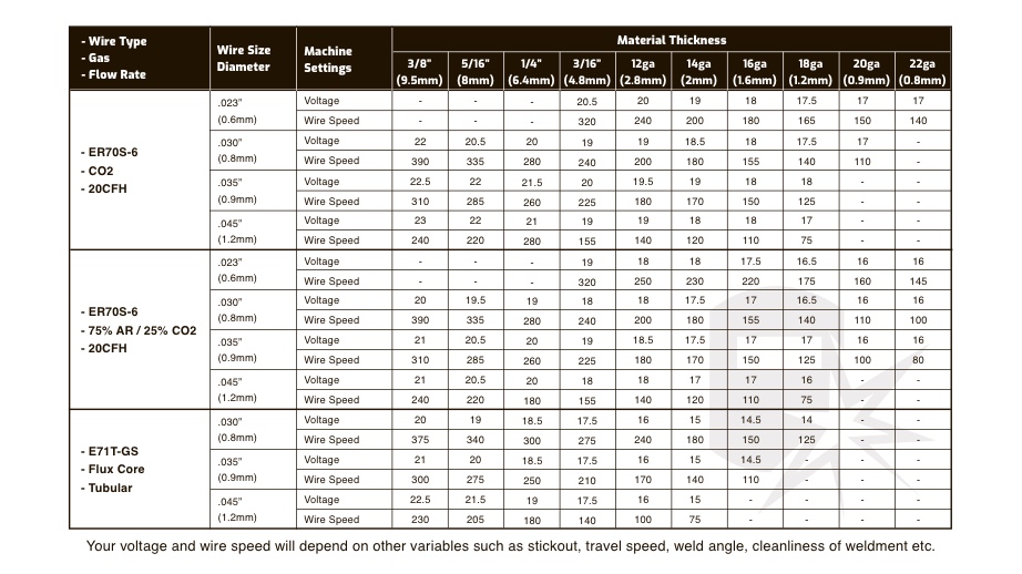
Starting with incorrect voltage and wire feed speed creates immediate frustration and wasted materials. Proper parameter selection depends on three key factors: material thickness, wire diameter, and joint configuration.
For 18-gauge steel with .023″ wire, begin with 14-16 volts and 180-220 inches per minute wire feed speed. Thin materials require lower settings to prevent burn-through while maintaining adequate penetration.
When welding 1/8-inch steel with .035″ wire, start at 18-20 volts with 250-280 IPM. Thicker materials need higher settings to achieve proper fusion through the joint without excessive buildup.
Adjust for Different Welding Positions
Reduce voltage by 1-2 volts when welding vertically or overhead to control the weld pool. Gravity affects molten metal flow in these positions, requiring slightly lower heat input to prevent sagging.
Increase wire feed speed by 10-15 IPM for out-of-position welding to maintain consistent amperage as you reduce voltage. This compensates for the shorter arc length typically used in vertical and overhead positions.
Test Settings on Scrap Metal First
Never begin your actual project without testing parameters on matching scrap material. A quick test weld reveals problems before they ruin your workpiece and saves time correcting issues during critical welds.
Clean both sides of your test piece with a wire brush to remove contaminants that affect weld quality. Mill scale, oil, and rust create porosity that invalidates your parameter testing.
Make several test beads at different travel speeds while maintaining consistent gun angle (10-15 degrees push angle). A properly tuned system produces a steady “sizzling bacon” sound with minimal spatter and a smooth, consistent bead profile.
Evaluate Test Weld Quality
Examine your test welds for these critical indicators:
– Good penetration: The weld should fuse completely through thin materials without burning holes
– Proper bead shape: A slightly convex profile with smooth transitions to the base metal
– Minimal spatter: Less than 5-10 small droplets per inch of weld
– Consistent width: Uniform bead width along the entire test length
Adjust voltage in 1-volt increments based on test results—higher voltage for wider beads, lower for deeper penetration. Fine-tune wire feed speed to match the adjusted voltage for optimal metal transfer.
Implement Essential Safety Practices
MIG welding exposes you to multiple hazards that require proper protection. Skipping safety measures creates immediate risks and long-term health consequences that far outweigh the minor inconvenience of proper precautions.
Always wear an auto-darkening welding helmet set to shade #10 for thin materials or #12 for thicker sections. Never attempt to weld without proper eye protection—UV radiation causes “welder’s flash” that feels like sand in your eyes and requires medical attention.
Wear flame-resistant clothing that covers all exposed skin. Cotton work shirts treated with flame retardant provide adequate protection for light welding, while leather welding jackets suit more demanding applications. Remove all synthetic fabrics that can melt onto skin when exposed to sparks.
Ensure adequate ventilation by positioning a fan to draw fumes away from your breathing zone. For confined spaces or extended welding sessions, use a respirator rated for welding fumes. MIG fumes contain manganese compounds that can cause neurological damage with prolonged exposure.
Maintain Your System for Reliable Performance
Regular maintenance prevents 80% of common MIG welding problems and extends equipment life. A clean, well-maintained system performs consistently while reducing downtime for troubleshooting.
Replace contact tips when the orifice becomes noticeably larger than your wire diameter—typically after 3-6 hours of continuous welding. Worn tips cause erratic wire feeding and unstable arcs that ruin weld quality.
Clean drive rollers weekly with a wire brush to remove metal shavings and oil buildup. Wipe rollers with a dry cloth after cleaning to remove debris that could contaminate your wire.
Check gas flow rate at the beginning of each session by placing your hand over the gun nozzle while triggering the welder. You should feel steady, consistent gas flow—not pulsing or weak output that indicates regulator or hose problems.
Properly setting up your MIG welder with gas transforms frustrating welding attempts into clean, professional results. By selecting the right shielding gas for your material, securing connections properly, threading wire correctly, and fine-tuning parameters on scrap metal first, you’ll achieve consistent weld quality from your very first pass. Remember to implement essential safety practices and perform regular maintenance to keep your system performing reliably. With these setup fundamentals mastered, you’ll spend less time troubleshooting and more time creating strong, durable welds on every project. Start with these procedures before each welding session, and you’ll develop the muscle memory that makes professional-quality results second nature.
Leave a Reply