When your weld beads look inconsistent or your electrode keeps sticking, improper amperage settings are almost always the culprit. Selecting the right welding amperage transforms frustrating welding sessions into smooth, professional results—whether you’re working with thin sheet metal or thick structural steel. Getting amperage wrong causes everything from weak welds that fail under stress to burn-through that ruins expensive materials. This guide gives you the exact amperage ranges for common metals and thicknesses, plus practical testing methods to dial in perfect settings for any welding project. You’ll learn how to match amperage to your specific electrode size, material thickness, and welding process to achieve optimal penetration without damaging your workpiece.
Matching Amperage to Metal Thickness for Strong Welds
The foundation of proper amperage selection starts with understanding your base metal’s thickness. Too little current creates weak, cold welds that lack proper fusion, while excessive amperage burns through thin materials and creates brittle welds on thicker sections.
Mild Steel Amperage Guidelines by Thickness
For the most common welding material, follow these specific amperage ranges based on actual metal thickness measurements:
- 24-18 gauge (0.024-0.048 inches): 30-60 amps for tack welds, 40-70 amps for continuous welding
- 16-14 gauge (0.060-0.075 inches): 60-90 amps
- 12-10 gauge (0.105-0.135 inches): 90-125 amps
- 3/16 inch (0.1875 inches): 125-150 amps
- 1/4 inch (0.25 inches): 150-185 amps
- 5/16 inch (0.3125 inches): 185-220 amps
- 3/8 inch (0.375 inches): 220-250 amps
Pro Tip: Always measure your metal with calipers rather than guessing thickness—visual estimation errors cause most amperage mistakes with thin materials.
Aluminum Amperage Requirements for Clean Welds
Aluminum demands different amperage settings than steel due to its higher thermal conductivity and lower melting point:
- 1/16 inch: 70-90 amps (TIG) or 80-100 amps (MIG)
- 1/8 inch: 95-120 amps (TIG) or 110-135 amps (MIG)
- 3/16 inch: 125-150 amps (TIG) or 140-165 amps (MIG)
- 1/4 inch: 155-180 amps (TIG) or 175-200 amps (MIG)
Critical Note: Aluminum requires approximately 20-25% higher amperage than steel of equivalent thickness to compensate for rapid heat dissipation.
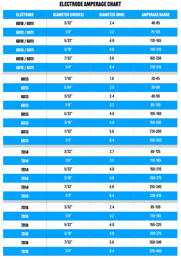
Electrode Size and Amperage Relationship Explained

Your electrode diameter directly determines the appropriate amperage range, regardless of welding process. Using the wrong electrode size for your amperage creates unstable arcs and poor weld quality.
Stick Welding (SMAW) Electrode Guidelines
| Electrode Diameter | Recommended Amperage Range | Best Applications |
|---|---|---|
| 1/16 inch | 30-80 amps | Sheet metal, thin gauge work |
| 5/64 inch | 60-110 amps | Automotive body work |
| 3/32 inch | 90-145 amps | General fabrication, 14-10 gauge |
| 1/8 inch | 130-185 amps | Structural steel, 3/16 inch+ |
| 5/32 inch | 180-230 amps | Heavy equipment repair |
Common Mistake: Using 1/8 inch electrodes on thin material—this forces excessive amperage that burns through. Downsize to 3/32 inch for better control on 16-12 gauge steel.
MIG Welding Wire Size Considerations
MIG welding requires matching wire diameter to both amperage and material thickness:
- .023 inch wire: 40-120 amps (24-16 gauge steel)
- .030 inch wire: 70-160 amps (18-12 gauge steel)
- .035 inch wire: 90-210 amps (14-1/4 inch steel)
- .045 inch wire: 150-300 amps (3/16 inch+ steel)
Expert Insight: When welding aluminum with MIG, use 75% argon/25% helium mix with .035 or .047 inch wire at higher amperage settings to maintain arc stability.
Process-Specific Amperage Settings for Different Welding Types
Each welding process has unique amperage requirements based on how the arc transfers metal to the workpiece.
TIG Welding Amperage Control Techniques
TIG welding offers precise amperage control through foot pedals or fingertip controls:
- Thin materials (under 1/8 inch): Start at minimum amperage and gradually increase until you establish a stable puddle
- Pulsed TIG: Use 30-50% background amperage during pulse off-cycle to maintain puddle without overheating
- DCEN (Direct Current Electrode Negative): Standard for steel/stainless—amperage directly controls penetration
- AC for aluminum: Balance control affects effective amperage—higher EN% increases cleaning action but reduces penetration
Pro Tip: For critical welds, set base amperage 10-15% below maximum for the thickness, then use pulsing to add penetration where needed without overheating.
MIG Welding Voltage and Wire Feed Speed Relationship
Unlike other processes, MIG requires coordinating voltage (amperage) with wire feed speed:
- Rule of thumb: For every 1 volt increase, increase wire feed speed by 2-3 inches per minute
- Burn-back issues: If wire keeps sticking in the nozzle, decrease wire feed speed while maintaining voltage
- Excessive spatter: Increase voltage while slightly reducing wire feed speed
- Poor penetration: Increase both voltage and wire feed speed proportionally
Troubleshooting Tip: When in doubt, set wire feed speed to mid-range for your material thickness, then adjust voltage until you hear a consistent “bacon frying” sound.
Testing and Verifying Correct Amperage Settings
Never rely solely on charts—always verify your amperage settings with physical tests on scrap material matching your actual workpiece.
The Visual Inspection Method
Weld a test bead on scrap material and examine these critical indicators:
- Proper amperage: Smooth, consistent ripples resembling fish scales with even edges
- Too low amperage: High, narrow bead with poor fusion at edges; electrode sticks frequently
- Too high amperage: Wide, flat bead with excessive spatter; possible burn-through on thin materials
Key Checkpoint: Break the test weld and examine the root—proper amperage shows complete penetration without excessive reinforcement.
Amperage Adjustment Workflow
Follow this systematic approach to dial in perfect settings:
- Start with recommended settings for your material thickness and electrode size
- Weld a 2-inch test bead on scrap of identical material
- Evaluate bead appearance and penetration
- Adjust in 5-amp increments—never jump more than 10 amps at a time
- Re-test after each adjustment until optimal results
- Document final settings for future reference on similar jobs
Expert Note: Ambient temperature affects amperage requirements—increase by 5-10 amps in cold conditions below 50°F (10°C).
Common Amperage Mistakes and How to Fix Them
Even experienced welders make critical amperage errors that compromise weld quality and safety.
The “Just Turn It Up” Misconception
Many beginners think higher amperage always means stronger welds, but excessive current creates:
- Brittle weld metal with reduced tensile strength
- Wider heat-affected zone that weakens base metal
- Distortion from excessive heat input
- Increased risk of cracking in high-strength steels
Solution: Always start at the lower end of recommended amperage range and increase only as needed for proper penetration.
Ignoring Joint Configuration Effects
Amperage requirements change dramatically based on joint design:
- Butt joints: Require standard amperage for thickness
- Lap joints: Need 10-15% less amperage (heat conducts into second layer)
- Outside corner joints: Require 5-10% more amperage (heat dissipates faster)
- Groove welds: Need 15-25% more amperage for root pass than fill passes
Critical Adjustment: For lap joints on 14 gauge steel, reduce amperage by 10-15 amps from standard butt joint settings.
Maintaining Consistent Amperage Performance
Environmental factors and equipment condition significantly impact amperage stability during welding.
Cable Length and Connection Impact
Longer welding cables increase electrical resistance, effectively reducing amperage at the arc:
- 10-foot cable: Minimal resistance (use standard settings)
- 25-foot cable: Reduce amperage setting by 5-8 amps
- 50-foot cable: Reduce by 12-15 amps from standard
- Poor connections: Add 10-20 amps to compensate for voltage drop
Prevention Tip: Keep all cable connections clean and tight—loose connections cause erratic amperage that creates inconsistent welds.
Electrode Storage and Condition Factors
Moisture-damaged or improperly stored electrodes require amperage adjustments:
- Damp electrodes: Increase amperage by 10-15 amps to burn off moisture
- Old electrodes: May require 5-10% higher amperage due to coating degradation
- Frozen electrodes: Always bake according to manufacturer specs before use
Safety First: Never compensate for damp electrodes by drastically increasing amperage—this creates dangerous hydrogen embrittlement risks in critical welds.
Final Amperage Optimization Checklist
Before starting your production welds, verify these critical amperage factors:
- [ ] Metal thickness measured with calipers, not estimated
- [ ] Electrode size appropriate for material thickness
- [ ] Test weld performed on identical scrap material
- [ ] Penetration verified through test weld breakage
- [ ] Adjustments made for cable length and connections
- [ ] Environmental conditions accounted for (temperature, wind)
- [ ] Joint configuration considered in amperage selection
Proactive Maintenance: Record successful amperage settings for common jobs in a welding logbook—this saves hours of trial and error on future projects with similar requirements. When working with unfamiliar materials, always start at the lower end of the amperage range and increase incrementally until you achieve the perfect weld bead profile and penetration. Remember that proper amperage selection isn’t just about making the weld—it’s about creating a joint that meets structural requirements while maintaining the integrity of your base materials.
Leave a Reply