A properly measured fillet weld determines whether your joint will hold under stress or fail catastrophically. Knowing how to use a fillet weld gauge correctly separates skilled welders from amateurs, ensuring your work meets structural specifications and safety standards. These precision instruments verify two critical measurements—throat thickness and leg length—that directly impact a weld’s load-bearing capacity. Without accurate gauge techniques, visually acceptable welds may lack sufficient strength, potentially causing dangerous structural failures in construction, pipeline, or manufacturing applications. This guide delivers the exact steps to measure fillet welds with professional accuracy using various gauge types, so you can confidently verify weld quality on any project.
Measure Throat Thickness Without Guesswork
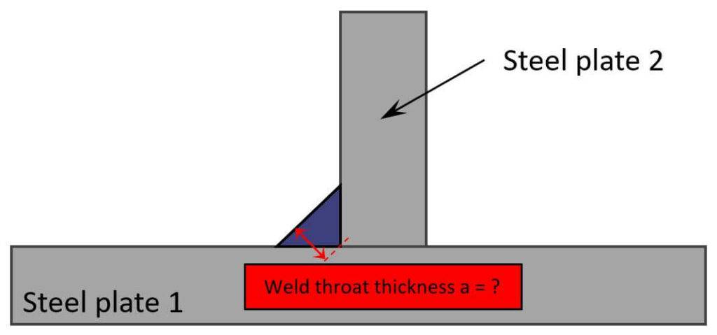
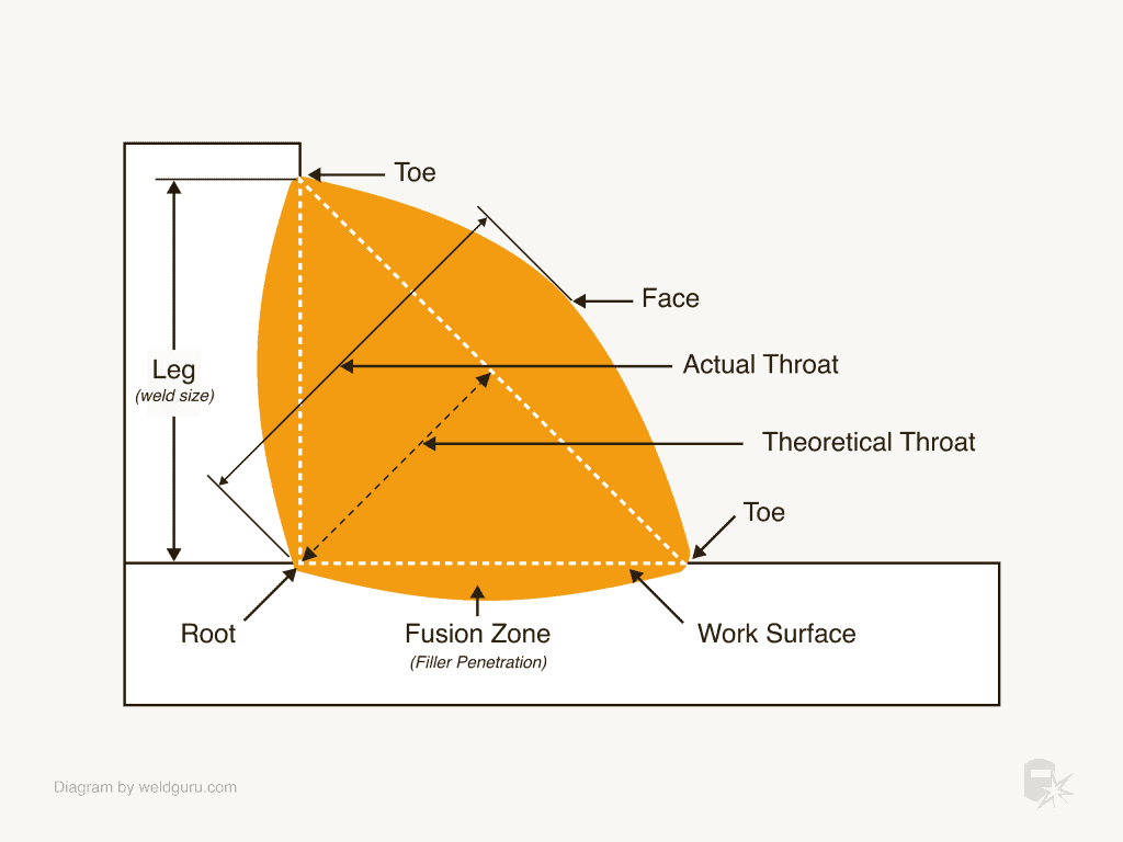
Throat thickness measurement determines your weld’s actual strength capacity, representing the perpendicular distance from the weld root to its face. Unlike leg length, throat thickness directly correlates to the weld’s ability to withstand stress forces. To measure throat thickness correctly with a fillet weld gauge, position the gauge against your weld so the central protrusion makes contact along the entire weld surface.
Critical visual indicators during throat measurement:
– ✅ Proper contact: No visible space between weld surface and gauge protrusion
– ❌ Undersized weld: Visible gap indicates insufficient throat thickness
– ❌ Concave weld: Never acceptable—reduces throat thickness below specifications
When measuring throat thickness, always check multiple points along the weld length as variations commonly occur between passes. If your gauge reveals concavity, add additional filler material to build the throat up to specification. For precise results, clean slag and spatter from the weld surface first—contaminants create false contact points that compromise measurement accuracy. Pro tip: Hold the gauge firmly against both base metals simultaneously to prevent tilting that would produce inaccurate readings.
Verify Leg Length with Precision
Leg length measurement confirms whether your weld extends properly along both joint surfaces, determining overall weld size and coverage. To check leg length accurately, slide your fillet weld gauge so it rests firmly against the vertical metal piece while maintaining full contact with the horizontal surface.
Two critical contact points to verify:
– Horizontal Toe (H. Toe): If space exists here, your weld is undersized horizontally
– Vertical Toe (V. Toe): If weld doesn’t reach this marker, it’s undersized vertically
Both measurements must meet specifications for proper joint strength. Many welding codes specify minimum leg lengths based on base metal thickness—never assume visual adequacy. Expert note: On multiple-pass welds, measure leg length after final pass only, as intermediate measurements will be inaccurate. For best results, take measurements at 6-inch intervals along the weld to identify any inconsistencies that might indicate technique problems.
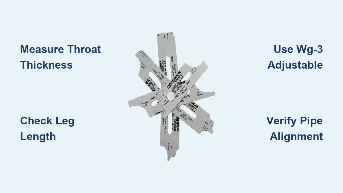
Master the WG-3 Adjustable Gauge Technique
The WG-3 adjustable fillet weld gauge measures any fillet weld from 1/8″ to 1″ with 1/32″ accuracy using a single instrument. This versatile tool eliminates the need for multiple specialized gauges while fitting conveniently in your shirt pocket (2-1/4″ x 3″, 1-1/2 oz).
Step-by-step WG-3 leg length measurement:
1. Slide the offset arm at 45° until it contacts the vertical leg toe
2. Tighten the four adjustment screws to lock position
3. Read measurement where arm meets scale (calibrated in 32nds)
For throat thickness measurement, adjust the internal pointer until it contacts the weld throat, then lock it in position. Time-saving shortcut: Mark common weld sizes on your WG-3 with permanent marker for instant visual reference during production welding—no need to read the scale for standard sizes.
Apply WG-4 Bridge Cam Gauge for Comprehensive Inspection
The WG-4 Bridge Cam Gauge measures eight critical parameters in one instrument, making it indispensable for thorough weld verification. This multi-function gauge checks angle of preparation (0-60°), excess weld metal, undercut depth, pitting depth, fillet weld throat, leg length, misalignment, and linear measurements up to 2″.
Effective WG-4 usage technique:
– Position the bridge across the weld crown for stability
– Rotate the dial until the probe contacts the weld surface
– Slide the pointer to the reference point
– Read measurement directly from dual-scale (inch/metric)
Pro tip: When measuring undercut depth, place the gauge perpendicular to the weld seam and lower the probe into the undercut area—this provides more accurate readings than parallel placement. The WG-4’s stable bridge design eliminates measurement errors common with handheld single-point gauges, especially on curved surfaces.
Use WG-5 V-WAC Gage for Regulatory Compliance
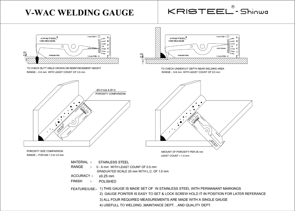
The WG-5 V-WAC Gage specializes in verifying compliance with NRC Visual Weld Acceptance Criteria, consolidating four essential measurements into one instrument. This gauge is critical for projects requiring nuclear, aerospace, or other high-consequence industry standards where precise documentation matters.
WG-5 measurement capabilities:
– Undercut depth to 1/32″ precision
– Porosity comparison (1/8″ and 1/16″ sizes)
– Porosity frequency per linear inch
– Crown height verification
When using the WG-5 for compliance verification, lock measurements in position with the retaining screw for documentation purposes. Expert note: For porosity assessment, compare multiple locations along the weld—acceptance criteria often specify maximum allowable porosity per foot of weld, not just per location.
Execute Pipe Alignment Measurements Correctly
Pipeline welding demands specialized measurement techniques with pipe-specific gauges. The WG-1 HI-LO Welding Gage measures internal pipe misalignment before and after tacking, reducing radiographic rejects during fabrication.
Four-step internal HI-LO measurement:
1. Unlock retaining screws and extend gauge legs beyond barrel
2. Insert legs into root gap, rotate 90° while applying back pressure
3. Hold gauge square with fitting, lock retaining screw
4. Read measurement at red line indicator
For root weld spacing with the WG-2 Economy Gage, insert the tapered leg into the root gap until it contacts both pipe edges, then lock and read the 1/32″ to 3/16″ scale. Critical reminder: Pipe alignment measurements must be taken before welding begins—once welding starts, these critical fit-up measurements become impossible to verify accurately.
Avoid These Common Measurement Mistakes
Even experienced welders make critical errors when learning how to use a fillet weld gauge. The most frequent mistake involves improper gauge positioning where the instrument doesn’t maintain full contact with both base metals during leg length measurement. This produces falsely high readings that may incorrectly indicate acceptable weld size.
Three measurement pitfalls to avoid:
– Measuring throat thickness on concave welds (always reject concave fillets)
– Failing to clean weld surface before measurement (slag creates false readings)
– Using gauges outside their specified range (WG-3 for throat measurements <1/8″)
Pro tip: Verify your gauge calibration weekly using a test piece of known dimensions—this simple step catches calibration drift before it causes costly rework or rejection of acceptable welds.
Maintain Your Fillet Weld Gauges for Longevity
Proper care of your fillet weld gauges ensures continued accuracy and extends their service life significantly. Stainless steel construction resists corrosion, but precision measurement surfaces require protection from damage.
Essential gauge maintenance practices:
– Store in protective case after each use (never leave on workbench)
– Wipe clean with dry cloth to remove weld spatter and debris
– Verify calibration weekly against known standards
– Keep separate from other tools to prevent scratching measurement surfaces
Expert note: If you notice inconsistent measurements, check for microscopic burrs on gauge edges—these can be carefully removed with a fine honing stone without affecting calibration. Regular maintenance preserves the precision contact surfaces necessary for accurate measurements throughout the gauge’s service life.
Mastering how to use a fillet weld gauge properly transforms your welding from guesswork to precision craftsmanship. Whether you’re verifying throat thickness on structural beams, checking leg length on pipe welds, or ensuring compliance with nuclear standards, proper gauge technique determines whether your welds provide adequate strength. Remember that accurate measurement depends on proper positioning, regular gauge maintenance, and awareness of common pitfalls. By implementing these techniques consistently, you’ll produce welds that not only look good but meet critical specifications for strength and safety in every application. The next time you pick up your fillet weld gauge, approach it not just as a measuring tool, but as your quality assurance partner that verifies every weld meets the standards your projects demand.
Leave a Reply