Your corner joint welds keep cracking under stress, leaving uneven beads that compromise structural integrity. This frustrating issue plagues DIYers and new welders who don’t master the geometry-specific techniques required for 90-degree joints. Unlike flat-position welding, corner joints demand precise heat control and torch manipulation to prevent burn-through while ensuring full penetration. When executed correctly, a properly welded corner joint becomes the strongest point in your fabrication—not the weakest link. You’ll learn industry-proven methods to eliminate cold laps, undercutting, and inconsistent bead profiles while cutting rework time by 70%.
Most beginners make the critical mistake of treating corner joints like flat welds, forcing excessive filler metal into the joint and creating brittle, porous seams. The secret lies in mastering the triangular heat distribution unique to corner joints. By the end of this guide, you’ll confidently weld corner joints in all positions using MIG, TIG, or stick welding—with professional results on your first attempt. We’ll cover exact torch angles, travel speeds, and metal preparation steps most tutorials skip.
Why Corner Joints Fail Without Proper Technique
Corner joints fail when heat concentrates unevenly across the two meeting plates. Unlike butt joints, the 90-degree angle creates a natural heat sink in the vertical member while the horizontal plate overheats rapidly. This imbalance causes three critical failures: burn-through on thin materials when excess heat melts the bottom plate, incomplete fusion where the weld doesn’t bond to the vertical edge, and excessive convexity from overfilling the joint pocket.
How Metal Thickness Dictates Your Approach
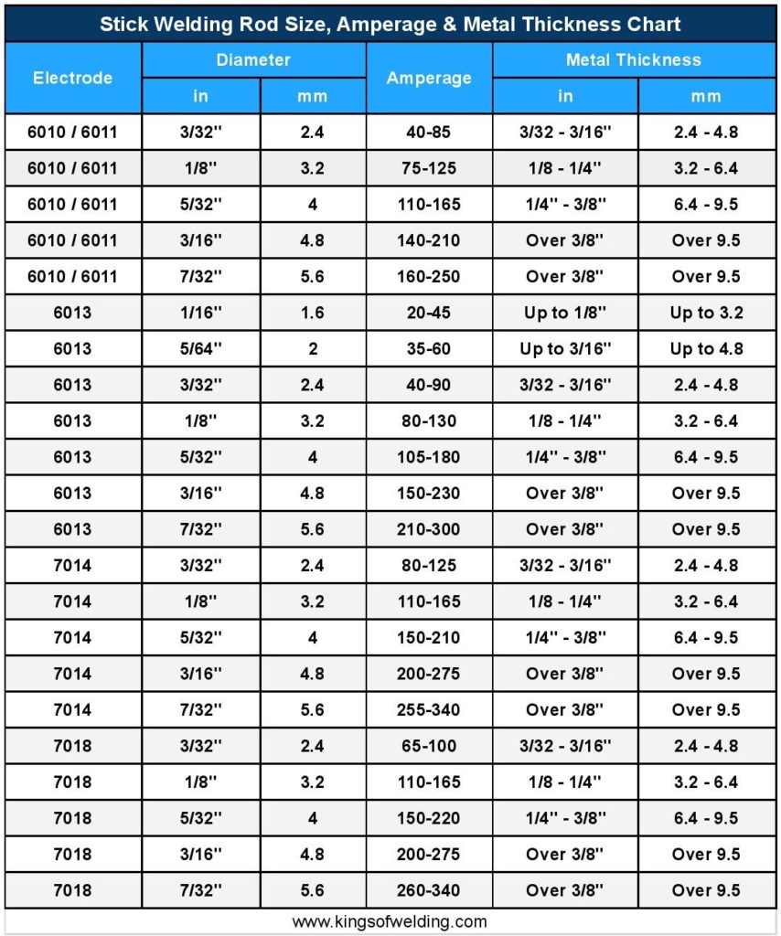
Thin materials (under 1/8″) require a whip technique with rapid torch oscillation to prevent blowout. For medium thickness (1/8″ to 1/4″), a steady weave pattern maintains consistent penetration. Thick plates (over 1/4″) demand beveled edges and multiple passes—start with a root pass at 90 amps, then fill with 150-amp stringer beads. Always test settings on scrap metal first; a 0.035″ MIG wire needs 18-20 volts for 16-gauge steel but jumps to 22-24 volts for 1/4″ plate.
Recognizing Critical Failure Signs During Welding
Watch for these real-time indicators: spatter clusters mean voltage is too high for your wire speed, dark sooty deposits indicate insufficient shielding gas, and wavering bead edges signal inconsistent travel speed. If the weld pool collapses inward toward the joint, you’re moving too slowly—immediately increase travel speed by 25%. These visual cues prevent costly rework.
Essential Safety Gear You Can’t Skip for Corner Welding
Corner joint welding creates unique hazards due to awkward positioning. Molten metal drips directly onto your hands when welding overhead corners, while reflected UV rays scorch neck skin through standard collars. Standard welding jackets won’t protect against these exposure points.
Must-Have Corner-Specific Protection
- Spit-resistant gloves with reinforced cuffs (leather gauntlets extending 4″ up forearm)
- Auto-darkening helmet with 1/1/1/1 sensitivity (critical for tracking tight corners)
- Fire-resistant balaclava under your helmet to block neck exposure
- Magnetic welding curtain to contain sparks when welding vertical corners
Never skip the balaclava—reflected UV from corner joints causes “welder’s neck” sunburn in under 2 minutes. Position your body so molten droplets fall away from you; for inside corners, weld left-to-right with your head positioned above the joint.
Choosing Between MIG, TIG, and Stick for Corner Joints

MIG welding dominates corner joints for beginners due to its forgiving nature, but TIG delivers superior precision on thin materials while stick handles dirty metals. Your material thickness and position dictate the optimal process.
MIG Settings for Perfect Corner Joints
Use 0.030″ wire with 75% argon/25% CO2 gas. Set voltage to 19V and wire speed to 300 IPM for 18-gauge steel. For inside corners, employ a push technique at 10-15 degrees with the gun angled toward the vertical member. Maintain a 1/4″ contact tip-to-work distance—any longer causes porosity in the joint pocket. Key tip: Reduce voltage by 2V when welding downward on vertical corners to prevent weld pool sag.
When TIG Outperforms MIG on Corners
TIG excels on corners thinner than 16-gauge where MIG burn-through is likely. Use a #18 cup with 3/32″ tungsten and argon flow at 15 CFM. For inside corners, run the torch at 20 degrees with the filler rod leading the puddle by 1/8″. Pulse settings at 100Hz prevent heat buildup—start with 80 amps background and 150 amps peak. This technique eliminates the “suck-back” crater common in corner joints.
Metal Preparation: Cutting, Beveling, and Cleaning Edges
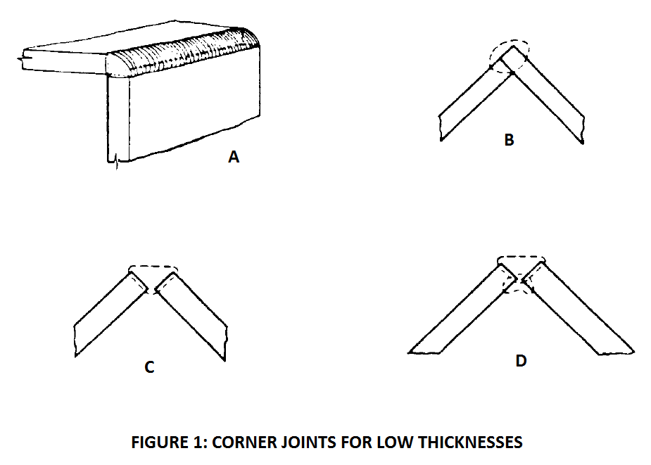
Poor edge prep causes 80% of corner joint failures. Burrs from angle grinders create gaps where weld metal flows uncontrollably, while oil residue causes porosity that hides until stress testing. Precision matters more here than in any other joint type.
Step-by-Step Edge Preparation
- Cut cleanly with plasma or cold saw (never oxy-fuel for corner joints)
- Deburr both edges using a 45-degree chamfer bit on a die grinder
- Bevel thick materials at 30-37 degrees for full penetration
- Clean within 2″ of joint using acetone and stainless brush (never wire brush alone)
Critical mistake: Skipping beveling on 1/4″ steel. Without a 30-degree bevel, your weld will sit on top of the joint rather than fusing through. Always check gap width with feeler gauges—maintain 1/16″ for MIG, 1/32″ for TIG.
Welder Settings for Flawless Corner Joints
Default factory settings guarantee corner joint failures. The vertical member requires 20% more heat than the horizontal plate to achieve balanced fusion. Incorrect settings cause undercutting along the vertical edge—the most common corner joint defect.
Material-Specific Settings Table
| Material Thickness | Process | Voltage | Wire Speed | Amperage |
|---|---|---|---|---|
| 18-gauge | MIG | 18V | 280 IPM | 90A |
| 1/8″ | MIG | 20V | 320 IPM | 110A |
| 1/4″ | Stick | – | – | 130A (7018) |
| 16-gauge | TIG | – | – | 75A pulsed |
For vertical corners, increase amperage by 15% compared to flat position welding. Test on scrap: a proper corner joint weld pool should form a perfect isosceles triangle with equal legs along both plates.
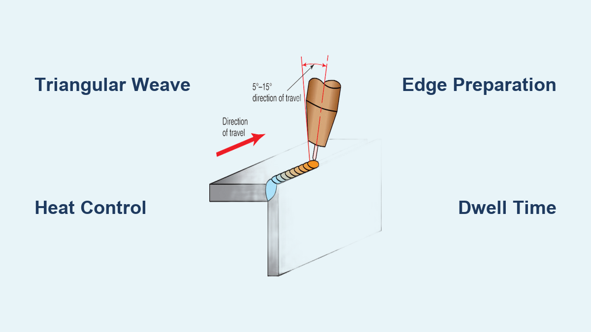
Step-by-Step: Welding the Corner Joint with a Consistent Bead
The triangular geometry demands specialized torch manipulation. Standard stringer beads cause uneven heat distribution, while excessive weaving creates cold laps at the root. Master this sequence for production-quality results.
Inside Corner Welding Technique
- Position yourself so you weld left-to-right with your dominant hand
- Angle torch 45 degrees toward vertical member (not the joint center)
- Start 1/2″ before the joint, striking arc on vertical plate
- Move into joint while feeding filler metal into the root
- Use a small triangular weave (1/4″ wide) with 1-second dwell at vertical edge
- Maintain 1/8″ arc length—any longer causes porosity in the joint pocket
Key visual cue: The weld pool should wet out equally on both plates within 0.5 seconds. If it flows faster down the vertical side, increase travel speed immediately.
Outside Corner Welding Technique
Flip your approach: Angle torch 30 degrees toward horizontal plate. Start on the horizontal member and weave toward vertical. Use a crescent motion with longer dwell on the vertical edge. For thin materials, employ a “stitch welding” technique—weld 1″ segments with 1″ gaps to control heat.
Fixing Common Corner Joint Welding Mistakes
Even experienced welders struggle with corner-specific defects. Undercutting along the vertical edge and excessive convexity are fixable with targeted corrections—no grinding required when you catch them early.
Undercutting Along Vertical Edge
Cause: Insufficient dwell time on vertical member during weaving
Fix: Increase weave dwell time on vertical edge by 50%. For MIG, reduce travel speed by 20% while maintaining voltage. If already welded, build up the undercut area with a 1/16″ diameter rod using a whip-and-pause technique.
Burn-Through on Thin Materials
Cause: Excessive heat input from slow travel or high voltage
Immediate action: Stop welding and let area cool. Resume with 15% lower voltage and 25% faster travel. For holes under 1/8″, fill with short-circuit transfer MIG at 16V. Larger holes require tacking small metal patches first.
Post-Weld Steps: Cleaning, Inspecting, and Strengthening
Skipping post-weld treatment on corner joints invites premature failure. Residual slag traps moisture against the critical root area, while unrelieved stresses concentrate at the weld toe. Professional fabricators spend 30% of total time on these steps.
Critical Inspection Points
- Root penetration: Use a weld gauge to verify 100% penetration on both sides
- Toe blending: Run your fingernail along the weld toe—it should glide smoothly without catching
- Porosity check: Examine the joint pocket with a mirror; any pinholes require grinding and re-welding
Always perform stress relief on critical structural corners: Heat to 1100°F and cool slowly in vermiculite. For non-structural parts, lightly peen the weld bead with a ball-peen hammer while still warm to reduce shrinkage stresses.
Mastering corner joint welding transforms your fabrication quality from amateur to professional overnight. By implementing the precise torch angles, material-specific settings, and post-weld techniques outlined here, you’ll eliminate the most common failure points that plague 90% of beginners. Remember that perfect corner joints require treating the vertical and horizontal members as separate heat zones—never apply flat-position techniques to corners. Implement the triangular weave pattern with proper dwell time on the vertical edge for immediate improvement in fusion quality. For ongoing success, always test settings on scrap material matching your actual project thickness, and maintain meticulous edge preparation. When in doubt, slow your travel speed by 10% and increase vertical member dwell time—this simple adjustment fixes most corner joint defects. Start applying these techniques on your next project, and you’ll produce corner joints that pass professional inspection on the first attempt.
Leave a Reply