That frustrating moment when your T-joint weld fails under minimal stress despite looking perfect? You’re not alone. When learning how to weld at joint configurations correctly, many welders struggle with T-joints—the perpendicular connections where two metal pieces form a “T” shape. These joints appear everywhere from structural beams to table legs, yet improper technique creates weak points that compromise entire projects. The difference between a solid connection and a failure point comes down to mastering specific techniques that ensure complete fusion through the joint thickness.
Understanding how to weld at joint arrangements properly separates competent welders from professionals. Most beginners make the critical mistake of focusing only on surface appearance while neglecting penetration—the depth where filler metal fuses with both base materials. Without adequate penetration, your T-joint has only surface adhesion, creating what looks like a solid weld but fails catastrophically under load. This guide reveals exactly what you need to know to create reliable T-joint connections every time, whether you’re working with thin sheet metal or thick structural steel.
Why Your T-Joint Welds Keep Failing
Inadequate Penetration Causes Hidden Weaknesses
That smooth, shiny T-joint weld on your project might look professional, but if it lacks proper penetration, it’s essentially glued together rather than fused. Penetration—the depth where filler metal bonds with both base materials—determines actual joint strength more than any other factor. When learning how to weld at joint configurations, most beginners focus on bead appearance while neglecting this critical internal quality.
T-joints present unique penetration challenges because the horizontal base member acts as a heat sink, drawing energy away from the critical joint intersection. This thermal imbalance often leaves the root of the joint unfused while creating a bead that appears adequate on the surface. The resulting weak point fails under stress that the base metal could easily handle, causing frustrating project failures that seem inexplicable until you understand what’s happening beneath the surface.
Pro Tip: Test your penetration by grinding a small section of your practice welds. Properly fused T-joints show consistent weld metal extending through the joint intersection, while inadequate welds reveal a visible separation line between the pieces.
Lamellar Tearing: The Silent T-Joint Killer
Lamellar tearing represents the most serious threat to T-joint integrity, especially in structural applications. This insidious failure occurs when inclusions in the base metal combine with tensile stress from welding shrinkage to create cracks parallel to the weld direction. Unlike surface cracks that you can spot during inspection, lamellar tearing happens within the base metal itself, often remaining invisible until the joint fails catastrophically.
Materials with high sulfur content or laminar inclusions—common in rolled steel plates—are particularly vulnerable. The perpendicular orientation of T-joints creates ideal conditions for this failure mode because the weld shrinkage stress acts perpendicular to the material’s weak planes. Preventing lamellar tearing requires both proper material selection and welding techniques that minimize residual stress.
Critical Safety Steps Before Welding T-Joints
Essential PPE for T-Joint Welding
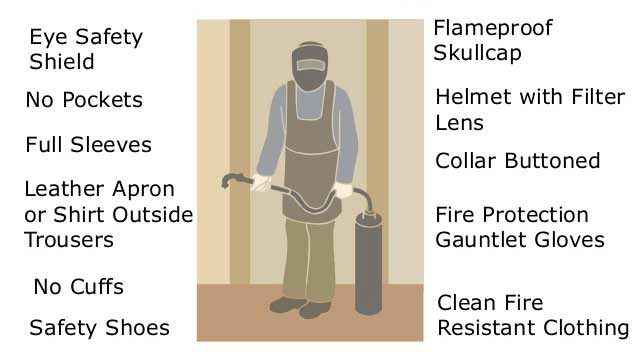
Before striking your first arc on a T-joint, verify you have proper personal protective equipment. A welding helmet with shade 5-8 lens protects against arc radiation that can cause “welder’s flash” even with brief exposure. Flame-resistant gloves shield hands from spatter that inevitably occurs when how to weld at joint configurations with proper technique. Cover all exposed skin with cotton or leather clothing—synthetic fabrics melt on contact with sparks.
The horizontal surface of T-joints creates unique hazards: spatter falls directly onto your legs and feet when welding overhead positions. Steel-toed boots with high tops provide essential protection against these falling sparks. Never skip eye protection underneath your helmet—grinding preparation creates metal particles that can cause serious eye injuries if not properly shielded.
Grounding Verification for Stable Arc Performance
Improper grounding causes more T-joint welding failures than most beginners realize. Before starting, clean a dedicated spot on the horizontal base member for your work clamp connection. Remove paint, rust, and mill scale to expose bare metal—this ensures consistent electrical contact that prevents arc instability.
Test your ground connection by attempting to strike an arc on scrap metal. A healthy arc starts cleanly with minimal spatter. Erratic starting, excessive spatter, or inconsistent arc behavior indicates poor grounding that will ruin your T-joint weld quality. For T-joints specifically, attach the ground clamp to the horizontal member near the weld area rather than at the far end—this reduces electrical resistance through the joint.
Metal Preparation Checklist for Perfect T-Joints

Surface Cleaning Protocol That Prevents Porosity
Contaminants cause 80% of T-joint welding failures, yet most beginners rush this critical step. Use an angle grinder with a clean abrasive disc to remove all mill scale, rust, oil, and paint from both the vertical edge and the horizontal surface within 1 inch of the joint. Pay special attention to the corner intersection—this area traps contaminants that create porosity when heated.
Common Mistake: Using the same grinding disc for multiple materials transfers contaminants. Dedicate specific discs for stainless steel, aluminum, and carbon steel to prevent cross-contamination that causes weld defects. After grinding, wipe the joint with acetone on a clean rag to remove any remaining oils before welding.
Edge Preparation Guidelines by Material Thickness
Material thickness determines whether you need edge preparation before learning how to weld at joint configurations:
- Under 3mm: No bevel needed—clean surfaces thoroughly
- 3-6mm: Square edges with tight fit-up (less than 1mm gap)
- 6-12mm: 45-degree V-bevel on vertical member
- Over 12mm: J-bevel for optimal penetration
For thicker materials, beveling creates space for the arc to reach the joint root. A V-bevel requires more filler metal but can be created with basic tools, while a J-bevel provides superior penetration access but needs specialized equipment. Always bevel the vertical member only—this maintains the full thickness of the horizontal base member that provides critical structural support.
Single-Pass T-Joint Technique for Thin Materials
Electrode Angle and Travel Speed Balance
For materials under 6mm thick, a single-pass fillet weld often suffices when how to weld at joint connections properly. Position your electrode at 45 degrees from the horizontal surface, pointing directly at the joint intersection. Maintain a slight drag angle (5-15 degrees backward from travel direction) to direct arc force into the weld pool rather than pushing molten metal ahead.
Travel speed makes or breaks single-pass T-joints. Move too fast and you’ll get a narrow, convex bead with inadequate penetration. Move too slow and the weld pool becomes oversized, risking burn-through on thin materials. The ideal speed produces a bead width approximately 3 times the electrode diameter with a slightly convex profile rising 1-2mm above the base metal.
Pro Tip: Practice on scrap material first—run several test beads while adjusting your speed until you achieve consistent width and penetration. Mark your ideal speed on the workpiece to replicate it during actual welding.
Multi-Pass T-Joint Welding for Maximum Strength
Root Pass Technique That Ensures Complete Fusion
Thicker materials require multi-pass techniques to achieve proper penetration when how to weld at joint configurations. The root pass establishes the foundation—any defect here compromises the entire joint. Position the electrode at 45 degrees and run a straight bead down the joint intersection with minimal weaving. This critical pass must show visible fusion on both sides of the joint—look for the “wetting” action where molten metal flows into both base materials.
After completing the root pass, chisel off the slag and inspect for complete fusion. If you see any gaps or lack of fusion at the root, grind out the defective section completely before proceeding. Never build additional passes over a poorly fused root—the resulting joint will fail under load regardless of subsequent passes.
Weave Pattern Selection for Optimal Buildup
Choose your weave pattern based on required weld size:
- Small fillets (under 6mm): Stringer beads with minimal oscillation
- Medium fillets (6-10mm): Zig-zag weave with pauses at edges
- Large fillets (over 10mm): Circular or crescent weave patterns
When using weave techniques, maintain consistent contact with both previous pass edges as visual guides. Pause briefly at each edge (about 1 second) to allow proper fusion before moving to the opposite side. This prevents undercut—the groove that forms along the weld edge that significantly reduces joint strength.
Electrode Angle Secrets for Perfect T-Joint Penetration

Angle Adjustment by Pass Type
Electrode angle directly controls heat distribution between the vertical and horizontal members. Master these angle adjustments for professional T-joint results:
- Root pass: 45 degrees for balanced heating of both members
- Fill passes: 50-60 degrees to direct more heat into horizontal member
- Cover pass: 30-40 degrees to prevent undercut on vertical member
The vertical member requires more heat input than the horizontal base because it has less thermal mass. Steeper angles (50-60 degrees) during fill passes compensate for the horizontal member’s heat-sinking effect. For the final cover pass, shallower angles (30-40 degrees) direct heat inward rather than toward the vertical edge, preventing undercut that creates stress concentration points.
Warning: Letting your angle drift during welding creates inconsistent penetration. Develop muscle memory by practicing angle maintenance on scrap metal before attempting critical joints.
Choosing the Right Electrode for T-Joint Welding
E6013 Electrode Settings by Material Thickness
E6013 electrodes provide the ideal balance of ease-of-use and performance when learning how to weld at joint configurations:
- 3-6mm material: 2.5mm (3/32″) electrode at 70-90 amps
- 6-10mm material: 3.25mm (1/8″) electrode at 100-120 amps
- Over 10mm material: 4.0mm (5/32″) electrode at 130-150 amps
T-joints require 10-15% higher amperage than butt joints at the same thickness because the horizontal member conducts heat away from the joint. Test your settings on scrap material first—proper amperage produces a stable arc with moderate spatter and easy slag removal. Low amperage creates a stubby, difficult arc that sticks frequently; high amperage causes excessive spatter and undercut.
Troubleshooting Common T-Joint Welding Problems
Eliminating Undercut on Vertical Member Edges
Undercut along the vertical member’s top edge represents the most common T-joint defect. This groove reduces effective material thickness and creates a stress concentration point that causes premature failure. Fix undercut by:
- Reducing travel speed to allow more filler deposition at edges
- Decreasing amperage if undercut appears despite proper speed
- Using shallower electrode angles (30-40 degrees) on final passes
- Pausing briefly at each edge during weave patterns
Pro Tip: When running cover passes, imagine you’re “feathering” the edge rather than cutting into it. The electrode should direct heat slightly inward from the edge rather than directly at it.
Achieving Consistent Penetration Through Joint Thickness
Inconsistent penetration creates weak spots that compromise entire T-joint connections. Ensure complete fusion by:
- Verifying root pass penetration before adding subsequent layers
- Maintaining consistent travel speed—use a straightedge guide if needed
- Increasing amperage 10-15% above butt joint recommendations
- Using proper edge preparation for materials over 6mm thick
For critical applications, perform a break test on practice welds. A properly fused T-joint should fracture through the base metal rather than separating at the weld interface.
Finishing and Verifying T-Joint Weld Quality
Visual Inspection Checklist for Professional Results
After completing your T-joint weld, perform this verification process:
- Slag removal: Clean slag completely with chipping hammer
- Surface inspection: Check for cracks, porosity, or undercut
- Profile assessment: Measure leg size with fillet weld gauge
- Fusion verification: Confirm complete fusion at both toes
A quality T-joint weld shows smooth, regular ripples with no visible defects. The transition between weld metal and base metal (toes) should be gradual without sharp notches or gaps. Undercut should not exceed 0.5mm depth—if present, grind and reweld the affected section.
Post-Weld Treatment for Maximum Durability
Extend your T-joint’s service life with these finishing steps:
- Allow controlled cooling—don’t quench hot welds
- Remove sharp edges with grinding or filing
- Apply corrosion protection matching base material
- Perform stress relief if required for service conditions
For structural applications, grinding requires extreme caution—never reduce the weld throat thickness below design specifications. The fillet profile contributes significantly to joint strength, so focus grinding only on smoothing surface irregularities rather than reshaping the entire weld.
Advanced T-Joint Techniques for Professional Results
Double-Sided Welding for Thick Materials
For materials over 12mm thick, double-sided welding provides the most efficient path to full penetration. Complete the first side using proper multi-pass technique, then flip the workpiece and bevel the opposite side to remove the root of the first weld. This preparation allows the second side to achieve complete penetration through the entire joint thickness.
The double-sided approach reduces total heat input compared to building a massive single-sided weld, minimizing distortion and residual stress. It also creates a more favorable grain structure in the weld metal, enhancing toughness and fatigue resistance—critical for structural applications where how to weld at joint connections must withstand cyclic loading.
Practice Drills for T-Joint Mastery
Develop consistent T-joint skills through deliberate practice:
- Angle consistency drill: Weld while focusing only on maintaining perfect electrode angle
- Speed control exercise: Run beads between parallel lines at varying speeds
- Multi-pass progression: Build progressively larger fillets with proper sequencing
Document your successful parameters—amperage, angle, travel speed—for different material thicknesses. Create a reference chart you can consult when starting new projects. This systematic approach transforms T-joint welding from a frustrating challenge into a reliable skill you can deploy confidently on any project requiring strong perpendicular connections.
Leave a Reply