Welding cast aluminum presents unique challenges that distinguish it from working with standard aluminum alloys. The porous nature of cast aluminum, combined with its high silicon content and refractory oxide layer, requires specialized techniques, careful preparation, and the right filler materials to achieve strong, durable welds. Whether you’re repairing automotive engine components, marine parts, or aerospace fixtures, understanding the specific requirements of cast aluminum welding ensures successful results and prevents costly component replacement. This comprehensive guide walks you through every stage of the process, from initial material identification through final inspection, providing the knowledge needed to tackle cast aluminum welding projects with confidence.
Why Cast Aluminum Welding Requires Special Techniques
Cast aluminum fundamentally differs from wrought aluminum in ways that significantly impact welding procedures and outcomes. The casting process entraps gas within the material, creating a porous structure that can release bubbles during welding and form voids within the weld metal. This porosity weakens joints and creates cosmetic defects that compromise component integrity. Additionally, most cast aluminum alloys contain high silicon content—often 5-12%—which improves casting fluidity but reduces ductility and increases susceptibility to cracking under thermal stress.
Overcoming the Aluminum Oxide Challenge
The naturally occurring oxide layer on aluminum surfaces creates perhaps the most significant welding challenge. While the base metal melts at approximately 660°C, this oxide coating withstands temperatures exceeding 2000°C. If not completely removed immediately before welding, this layer prevents proper fusion between the filler and base metal, resulting in lack of fusion defects, inclusions, and compromised joint strength. The oxide reforms rapidly upon air exposure, meaning preparation must occur immediately before welding rather than during initial setup.
Managing Thermal Conductivity Issues
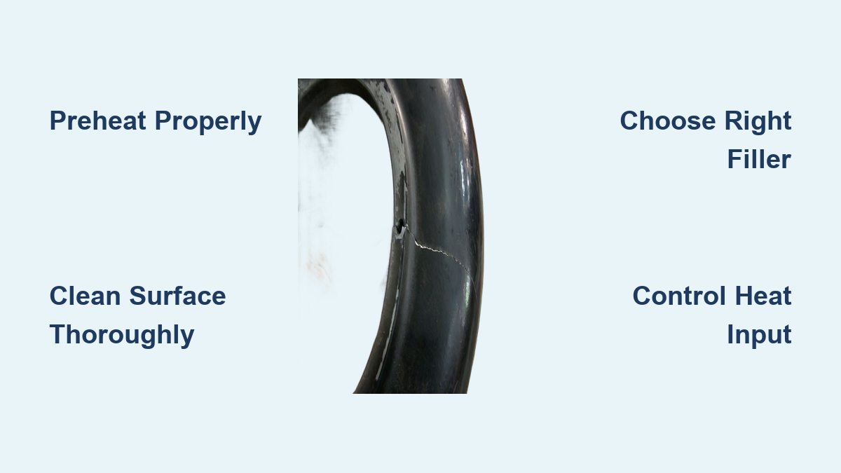
Thermal management presents another critical challenge when welding cast aluminum. The material’s high thermal conductivity causes rapid heat dissipation, making it difficult to maintain consistent temperatures at the weld joint. This characteristic necessitates preheating for thicker sections and requires welders to maintain steady, deliberate travel speeds to ensure adequate penetration without burning through thin areas. The combination of these factors—porosity, silicon content, oxide layers, and thermal conductivity—demands a systematic approach that addresses each challenge specifically.
Identify Your Cast Aluminum Alloy Before Welding
Positive alloy identification enables appropriate technique and filler material selection for successful cast aluminum welding. Visual inspection provides initial clues regarding alloy type, as certain alloys bear identifiable markings and surface characteristics. Porous or grainy surface appearances often indicate high silicon content, while exceptionally smooth finishes may suggest die casting origins. Components sometimes bear casting marks or manufacturer identifiers that provide alloy designation information.
Professional Alloy Identification Methods
Spark testing offers a quick, cost-effective preliminary identification method by analyzing the unique spark pattern produced during grinding. However, this technique lacks precision and provides only general alloy family identification rather than specific designation confirmation. For accurate results in professional welding environments, spectroscopic analysis using X-ray fluorescence (XRF) analyzers delivers precise alloy identification essential for critical applications. This capability proves particularly valuable when working with unknown cast components where filler material selection depends on base metal composition.
Common Cast Aluminum Alloy Families
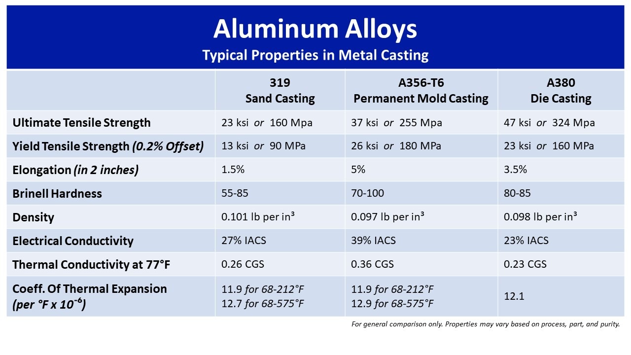
The most common cast aluminum alloy families include the 3XX.0 series alloys containing aluminum, silicon, and magnesium—with some variants like 319.0 also containing copper. These heat-treatable alloys weld readily using 4043 filler material and appear frequently in automotive and aerospace applications. The AlMg 5XX.0 series alloys, exemplified by 535.0, are not heat-treatable but weld excellently using 5356 filler material and provide superior corrosion resistance for marine environments. The 7XX.0 aluminum-zinc series alloys present significantly greater welding difficulty, with some variants considered unweldable due to their metallurgical properties.
Essential Pre-Weld Cleaning Procedures for Cast Aluminum

Thorough surface cleaning represents perhaps the most critical preparation step for cast aluminum welding. Contaminants including oil, grease, dirt, and machining residues lead directly to porosity, lack of fusion, and inclusions when trapped within the weld pool. The cleaning process must address both visible contamination and invisible surface residues that could compromise weld integrity.
Degreasing and Contaminant Removal
Degreasing requires non-chlorinated cleaners, as chlorinated products produce harmful gases when exposed to welding temperatures. Acetone followed by alcohol wipes effectively remove oils and residues without introducing problematic compounds. All cleaning chemicals must fully evaporate before welding commences, as trapped solvents create porosity during the welding thermal cycle. Work in a clean environment and avoid touching freshly cleaned surfaces with bare hands, as skin oils introduce contamination.
Oxide Layer Removal Techniques
The refractory oxide layer requires complete removal before welding using mechanical or chemical methods. Chemical cleaning using aluminum etching solutions containing phosphoric or hydrofluoric acid effectively removes oxide layers but requires strict safety precautions due to the hazardous nature of these compounds. Mechanical methods including sanding, grinding with fine-grit abrasives, or wire brushing with stainless steel brushes provide safer alternatives for oxide removal. Importantly, aluminum begins re-oxidizing immediately upon air exposure, making immediate welding following oxide removal essential for successful results.
Proper Preheat Techniques for Cast Aluminum Welding

Preheat temperature and application significantly affect cast aluminum welding success by reducing thermal shock, minimizing cracking risk, and improving weld penetration through uniform temperature distribution. For thick or complex cast aluminum components, preheating to 300°F–400°F (150°C–200°C) provides optimal results. Heating methods include propane torches for localized heating and ovens for uniform heating of complete components. Regardless of method, even heat distribution prevents thermal stresses that lead to cracking. Infrared thermometers or temperature-indicating crayons enable accurate temperature monitoring and prevent overheating that causes oxidation or warping.
Special Considerations for Heat-Treated Alloys
For heat-treated alloy castings, maximum preheat temperatures should remain below 275°F to prevent annealing and property degradation. Welding time on heat-treated components should limit to approximately five minutes or less to avoid overheating localized areas. Insulating blankets around the weld area reduce drafts and extend effective welding time by maintaining temperature. The preheated casting retains heat for 15-20 minutes after heating source removal, so use insulating blankets to maximize this window for welding.
TIG Welding Cast Aluminum: Step-by-Step Technique
Tungsten Inert Gas welding represents the preferred method for cast aluminum welding due to its precision and control capabilities. This process uses a non-consumable tungsten electrode and argon shielding gas to produce clean, high-quality welds with minimal spatter. The exceptional control over heat input and filler material addition proves crucial for preventing distortion and cracking in cast aluminum components.
Optimizing AC TIG Settings for Cast Aluminum
AC (alternating current) TIG welding provides essential capabilities for aluminum welding. The AC wave alternates between electrode positive and negative polarities, with the positive phase producing cleaning action that removes oxide from the work surface and the negative phase generating heat for penetration. Modern inverter-based TIG welders offer advanced AC wave manipulation capabilities including balance control, frequency adjustment, and independent amperage control for each half of the AC cycle.
Critical TIG Welding Parameters
Maintain consistent arc length approximately equal to one electrode diameter from the workpiece surface, and hold the filler rod at a 15-20° angle from the workpiece, creating a 90° angle between the filler rod and tungsten electrode. Use pure tungsten or zirconiated tungsten electrodes with ball tips for conventional TIG welders. Shield the weld pool with 100% argon gas at 15-20 cfm, or use 25/75 argon/helium mixtures for faster welding on thicker sections.
MIG Welding Cast Aluminum: Equipment and Settings

Metal Inert Gas welding offers faster welding speeds than TIG, making it suitable for larger projects and production work where efficiency matters. However, MIG welding on cast aluminum requires specialized equipment including spool guns or push-pull systems designed specifically for aluminum’s soft, easily deformed wire.
Overcoming Aluminum Wire Feed Challenges
Standard wire feed systems struggle with aluminum wire’s tendency to buckle and tangle, making proper equipment selection essential for successful results. Spool guns mount the wire spool directly on the gun handle, eliminating the long feed path that causes feeding problems. Push-pull systems use a motor in the gun handle to pull wire while a second motor in the wire feeder pushes it, providing consistent feed rates for aluminum wire over longer distances.
Optimal MIG Settings for Cast Aluminum
Use 100% argon shielding gas or argon-helium mixtures for enhanced penetration on thicker sections. Adjust wire feed speed and voltage to match material thickness, maintaining consistent travel speed for uniform bead appearance and penetration. The process provides less precise heat control than TIG welding, potentially leading to increased warping, spatter, and porosity in cast aluminum applications.
Selecting the Right Filler Alloy for Your Cast Aluminum
Filler material selection critically affects weld quality, strength, and corrosion resistance in cast aluminum welding. Filler materials are available as welding rods for TIG welding or welding wire for MIG welding, with selection depending on base metal composition and intended service conditions.
Matching Filler to Base Metal
4043 aluminum filler, a silicon alloy, represents the most common choice for high-silicon cast aluminum alloys including 356 and 319. This filler provides excellent fluidity, low shrinkage, and crack resistance, making it suitable for automotive, aerospace, and engine component applications. 5356 filler, a magnesium-based alloy, provides excellent corrosion resistance and produces stronger welds than 4043 in some applications. When welding components intended for marine environments or high-corrosion applications, 5356 often provides superior service life compared to silicon-based fillers.
Filler Material Storage Best Practices
Store filler materials in clean, dry areas away from moisture, oil, and dust contamination, and clean them before welding to remove oxidation or surface residues. Always wear clean gloves when handling filler materials to prevent contamination from skin oils. For thick sections or crack-prone alloys, slightly preheating filler rods enhances bonding and overall weld quality.
Step-by-Step Cast Aluminum Welding Process
Begin by applying preheat evenly to cast aluminum components at 300°F–400°F for most applications, adjusting based on section thickness and alloy type. Create small, evenly-spaced tack welds measuring 1/2 to 1 inch long along the joint to hold components in alignment during main welding. Start at one end and work toward the opposite end, maintaining consistent spacing between tacks. Use low amperage settings to minimize heat buildup and prevent the tacks from becoming starting points for cracking.
Executing the Primary Weld
Execute the primary weld using appropriate technique based on equipment and application requirements. Feed filler material steadily to ensure uniform weld bead formation, and shield the weld pool with 100% argon gas at 15-20 cfm. For thicker sections, use 25/75 argon/helium mixtures for faster welding and deeper penetration. Maintain consistent travel speed—too slow causes excessive heat buildup and potential burn-through, while too fast results in inadequate penetration.
Post-Weld Cooling Protocol
Allow welded components to cool gradually to prevent thermal shock that causes cracking or warping. Air cooling is preferred over rapid methods like water quenching. For thick castings, insulating blankets slow cooling and reduce thermal stress. The preheated casting retains heat for 15-20 minutes after heating source removal, so use insulating blankets around the weld area to reduce drafts and extend effective welding time.
Fix Common Cast Aluminum Welding Problems
Porosity in cast aluminum welds occurs when gas bubbles become trapped within the weld metal during solidification, creating small voids that weaken the joint. This condition commonly results from surface contaminants including moisture, oil, and dirt; inadequate shielding gas flow; welding in humid conditions; or excessive heat input that disrupts gas escape. Prevention requires meticulous surface cleaning using wire brushing, sanding, or chemical cleaners to eliminate contaminants before welding.
Preventing Cracking in Cast Aluminum Welds
Cracking in cast aluminum welds manifests in several forms requiring different prevention approaches. Hot cracking occurs during solidification when the weld metal lacks sufficient ductility to accommodate shrinkage stresses. Cold cracking appears after cooling when residual stresses exceed material strength. Prevent cracking through appropriate preheat temperatures, typically 200°F–400°F based on section thickness and alloy type. Select filler materials compatible with the base alloy to ensure proper metallurgical bonding and stress distribution.
Avoiding Burn-Through on Thin Sections
Burn-through occurs when excessive heat melts through the base material, creating holes particularly problematic in thin sections. Prevent burn-through by matching heat settings to material thickness and using appropriate travel speeds. Select filler materials appropriate for the application, and employ tacking to hold thin sections in position. Heat sinks and backing bars help conduct heat away from critical areas.
Post-Weld Inspection and Finishing for Cast Aluminum
Visual inspection provides the first level of weld quality assessment, revealing surface defects including cracks, porosity, undercuts, and incomplete fusion. Examine welds under good lighting conditions, looking for uniform bead appearance and appropriate toe blending with base metal. Surface porosity appears as small circular depressions on the weld face, indicating gas entrapment during solidification.
Professional Finishing Techniques
When dimensional tolerances or surface appearance requirements exist, machined or ground finishes bring the weld to final specifications. Use sharp cutting tools and appropriate speeds for aluminum to prevent burr formation and surface damage. Blend weld surfaces to match adjacent contours and textures, maintaining the component’s original geometry. Clean welding residue using stainless steel wire brushes, and consider post-weld heat treatment for high-stress components to relieve residual stresses and enhance mechanical properties.
Mastering cast aluminum welding requires understanding the unique challenges posed by this material family and applying systematic preparation, technique, and finishing procedures. The combination of proper material identification, meticulous surface preparation, appropriate filler selection, and controlled welding parameters enables successful repairs and fabrications that rival original component strength. With practice and attention to the details outlined in this guide, welders can confidently tackle cast aluminum projects ranging from automotive engine repairs to marine component restoration, extending component service life and reducing replacement costs.
Leave a Reply