When your vehicle’s engine mounts fail, welding new brackets directly to the frame offers a permanent solution many mechanics avoid due to concerns about stress fractures and vibration issues. These worries are legitimate but shouldn’t prevent you from completing a successful weld. With proper technique and attention to detail, welded engine mount installations can provide decades of reliable service without cracking or excessive vibration. This guide walks you through the complete process of how to weld engine mounts correctly, ensuring your project delivers professional-quality results that withstand daily driving stresses and performance demands.
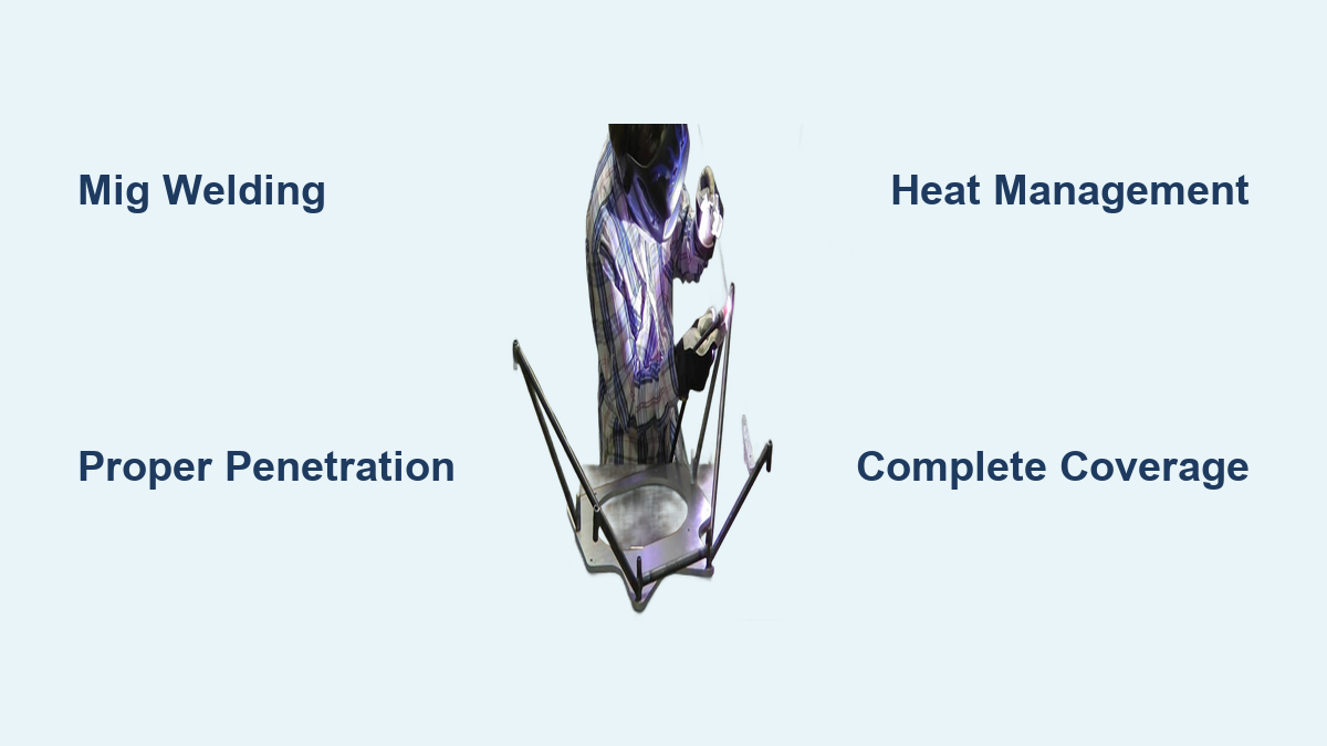
The fundamental principle behind successful engine mount welding is achieving adequate penetration while maintaining structural integrity. When performed correctly, a welded mount bracket becomes an integral part of the frame structure, capable of withstanding constant engine vibrations. Key factors determining your success include proper joint preparation, appropriate welding technique, correct heat management, and adequate weld geometry. Understanding these elements before you begin will help you avoid common mistakes that lead to weak or cracked welds that could compromise your vehicle’s safety.
MIG Welding Technique for Reliable Engine Mounts

MIG (Metal Inert Gas) welding stands as the most accessible method for how to weld engine mounts, offering clean welds with minimal slag and excellent penetration when executed properly. For most automotive applications, use a single-pass technique with .030-inch wire, which provides the ideal balance between deposition rate and control over the weld pool. If working with material thicknesses of 1/8-inch or greater, switch to .035-inch wire for better penetration in thicker frame rails.
Your critical technique adjustment involves turning up the heat sufficiently to “burn in” the weld, ensuring deep penetration into both the mount bracket and frame rail. Maintain a visible weld pool that demonstrates proper fluidity—indicating fusion with the base metal—rather than just seeing the weld bead remain hot while surrounding metal stays cool. A properly executed MIG weld should show uniform redness extending into both pieces being joined, confirming adequate heat transfer.
Pro Tip: Watch the color of the base metal adjacent to your weld pool. If only the weld bead remains bright red while surrounding metal stays dark, your heat setting is too low, creating a cold weld that lacks structural integrity—grind it out and restart with higher settings.
Complete Weld Coverage Protocol
Your weld must completely encircle the mount bracket, with special attention to corners and transitions where stress concentrations naturally occur. Avoid craters or incomplete weld sections near corners, as these represent stress risers where cracks can initiate over time. If defects occur during welding, grind them out thoroughly and reweld, but take care not to remove excess parent metal from the frame during cleanup operations.
Position the frame so it can be rotated during welding, allowing you to maintain optimal torch angle and travel direction throughout the process. Keep the majority of welding in a horizontal position to promote proper penetration and bead formation. For applications requiring a snug fit between the mount bolt and bracket, weld a washer to both sides of the shaft—this effectively reduces the effective diameter of the bolt hole, eliminating slop in the mounting system.
Alternative Welding Methods for Challenging Situations
Stick Welding for Maximum Penetration
Stick welding (shielded metal arc welding) offers a viable alternative when working in less-than-ideal conditions or with contaminated surfaces. Choose structural-grade electrodes rated for automotive steel applications, as they provide deeper penetration characteristics that help ensure fusion despite minor surface imperfections. While stick welding produces more slag requiring removal between passes, its tolerance of contamination makes it suitable for field repairs where perfect surface preparation isn’t possible.
Warning: Never begin welding on a vehicle without proper fire prevention measures. Keep a fire extinguisher nearby, clear all flammable materials from the work area, and have a helper watch for sparks landing in hidden locations—especially important when welding near engine mounts containing rubber components.
Flux-Core Wire Benefits and Limitations
Flux-core wire welding provides up to 30% more penetration than standard MIG configurations with gas shielding, making it advantageous when welding thicker mount brackets to thinner frame rails. This increased penetration helps ensure adequate fusion despite material thickness disparities. However, flux-core typically produces more spatter and requires more extensive cleanup of the finished weld, potentially adding significant time to your project.
Scab Plate Fabrication: The Professional Approach
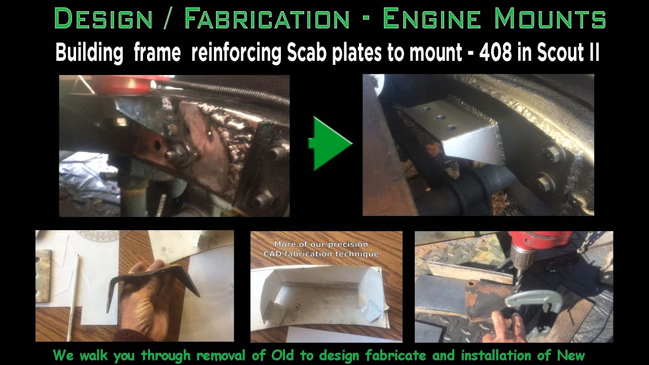
The scab plate technique represents the most reliable method for how to weld engine mounts in custom or modified applications. Fabricate your scab plates from steel between 1/16-inch and 3/32-inch thick—this provides adequate strength while remaining manageable during welding. Cut plates to approximately 4-inch by 6-inch dimensions to ensure substantial overlap with the frame rail, distributing stress more effectively across the frame structure.
When positioning the engine within the frame rails, consider multiple performance factors. Many builders push the engine as far forward as possible to keep heat away from the firewall while maximizing clearance for drivetrain components. Position the engine centerline approximately 12 inches from the frame rail (verify for your specific application), allowing the engine to sit high for maximum oil pan clearance while tucking the drivetrain close to the body.
Template Creation for Precision Mounting
Create accurate cardboard templates matching your motor mount’s dimensions and bolt pattern before cutting steel. Trace the design onto steel plate, leaving approximately 1/4-inch of extra material around the perimeter—this provides additional welding surface and ensures complete joint coverage. Drill bolt holes using step bits or specialized large-diameter drill equipment to accommodate the mount’s bolt shaft.
Before welding, remove all paint and surface contamination from both the mount and scab plate in welding areas. This cleaning is essential for proper fusion and preventing porosity. The rubber material in engine mounts doesn’t need removal, but be aware it’s flammable during welding. Begin with tacking components in position to prevent warping from heat buildup, then complete final weld passes while rotating the frame for optimal torch positioning.
Solid Motor Mount Conversion Performance Benefits
Converting from rubber-bushed mounts to solid welded mounts eliminates wheel hop during hard launches—a condition that damages transmissions and differentials while reducing traction. Vehicles with solid mounts experience firmer shifts due to the absence of engine torsional movement absorption. The performance results are significant: immediate power delivery to the drivetrain, eliminated wheel hop, and improved clutch engagement as the engine no longer twists away during engagement.
The trade-off is increased vibration transmitted through the drivetrain. While remaining rubber material helps absorb some vibration, overall levels increase compared to stock configurations. Most builders report this vibration as slight and manageable, particularly in performance vehicles where some vibration is expected. A full vehicle interior helps absorb vibration, reducing perceived intensity—especially important for daily drivers.
Heat Management to Prevent Warping

Strategic Tacking Sequence
Tacking components before final welding is essential for controlling warping. Place multiple small tacks in a pattern that holds components in proper alignment while allowing thermal expansion during final passes. Avoid large tacks that restrict movement and create stress points. Alternate tack positions on opposite sides of the joint to distribute heat more evenly and minimize distortion.
Multi-Pass Weld Sequencing
When multiple weld passes are required, apply them in a staggered pattern that distributes heat evenly. Alternate sides of the joint or build the weld in sections rather than continuous passes. This approach minimizes the tendency for the assembly to pull out of alignment as weld metal cools and contracts. Allow brief cooling periods between passes to prevent excessive heat buildup in the frame structure.
Professional Recommendations for Success
Training Investment Pays Off
Multiple experienced builders recommend obtaining proper welding training before attempting engine mount installations. Local career development centers offer courses covering both practical techniques and theoretical knowledge required for quality structural work. These classes typically include instruction on metallurgy, heat treatment, weld defect recognition, and safe practices—knowledge that transforms how to weld engine mounts from guesswork to precision work.
The MIG welding process is generally easier to learn than stick welding, particularly with gas shielding rather than flux-core wire. With gas shielding, resulting welds have minimal porosity and slag, requiring less cleanup and making inspection easier. The key skill involves learning to read the weld pool and understanding how travel speed and heat settings affect quality.
Mobile Welder Cost-Benefit Analysis
If you lack welding skills, hiring a mobile professional welder represents a practical alternative. Builders report paying around $60 for NASCAR-certified welders to complete installations that performed flawlessly for over 12 years under demanding 300+ horsepower conditions. This approach offers guaranteed quality, eliminates equipment costs, reduces project time, and lets you observe professional techniques—making it a smart investment compared to potential consequences of failed welds.
Long-Term Durability Assurance
Properly welded engine mounts should provide decades of reliable service. Periodically inspect welds during routine maintenance for cracks in the weld metal or heat-affected zone—address any signs immediately as cracks propagate rapidly under cyclic loading. After welding, paint the mount and surrounding area to protect against corrosion once the weld has cooled completely and cleanup is finished.
The concern about stress fractures is largely addressed through proper technique: good penetration, appropriate weld size, and complete joint coverage eliminate stress concentrations that lead to crack initiation. Factory welds on many vehicles last decades under similar conditions, proving that properly executed how to weld engine mounts procedures deliver lasting results when you follow these techniques. With correct execution, your welded engine mounts will withstand daily driving stresses and performance demands for the life of your vehicle.
Leave a Reply