Welding header collectors represents one of the most challenging yet critical skills in custom exhaust fabrication, where precision directly impacts performance and durability. When executed correctly, a properly welded header collector creates a seamless transition between primary tubes and exhaust outlet that withstands extreme heat cycles and constant vibration without developing leaks. This guide delivers actionable techniques used by professional fabricators to achieve leak-free collector welds on both mild steel and stainless steel headers, whether you’re building for street performance or dedicated race applications. You’ll learn exactly how to prepare, align, and weld header collectors using proven methods that prevent warping and ensure years of reliable service.
The collector serves as the critical junction where multiple exhaust primaries converge, and any weakness here will manifest as performance-sapping exhaust leaks that compromise engine efficiency. Whether you’re working with 0.065-inch mild steel tubing or premium 321 stainless for turbo applications, mastering header collector welding techniques transforms a functional exhaust system into a professionally crafted component. What follows is a comprehensive technical guide that provides step-by-step instructions for fabricators at all skill levels, with particular focus on the specific challenges of collector welding that differ from standard header tube work.
Differentiating Weld-On vs. Slip-On vs. True Merge Collectors

Selecting the right collector type before welding begins prevents costly mistakes and ensures optimal performance for your specific application. Each collector design requires fundamentally different welding approaches that directly impact the final quality and durability of your exhaust system.
Weld-on collectors feature a solid, formed piece that welds directly to all four header tubes with a star plug in the center. When properly executed, these collectors create fully sealed assemblies with zero potential leak points, making them ideal for custom builds where maximum exhaust integrity is required. The trade-off is significantly increased welding complexity, as all joints must be welded in place with limited access to certain areas.
Slip-on collectors consist of four short tubes (approximately two inches long) with a star plug, welded to a formed collector that slips over rather than being welded directly to the header tubes. Due to their design, slip-on collectors cannot be fully welded around all four tubes without causing fitment issues, limiting their use to open collector applications where exhaust exits directly after the collector. These provide adequate performance for many street applications but require different welding techniques than weld-on designs.
True merge collectors represent the highest-performance option, featuring four individual tubes miter-cut and physically merged together at precise angles (typically 15 degrees). The outlet diameter exceeds the merge point diameter, significantly improving exhaust flow. Genuine true merges are always slip-on style due to their complex geometry, and many products marketed as merge collectors are actually look-alikes with only a merge spike added, lacking true mitered merges that deliver measurable performance benefits.
Perfect Primary Tube Preparation for Seamless Collector Welds
Proper preparation of primary tube ends is non-negotiable for successful collector welding, as any irregularity will propagate through the entire assembly and create weak points in the finished product.
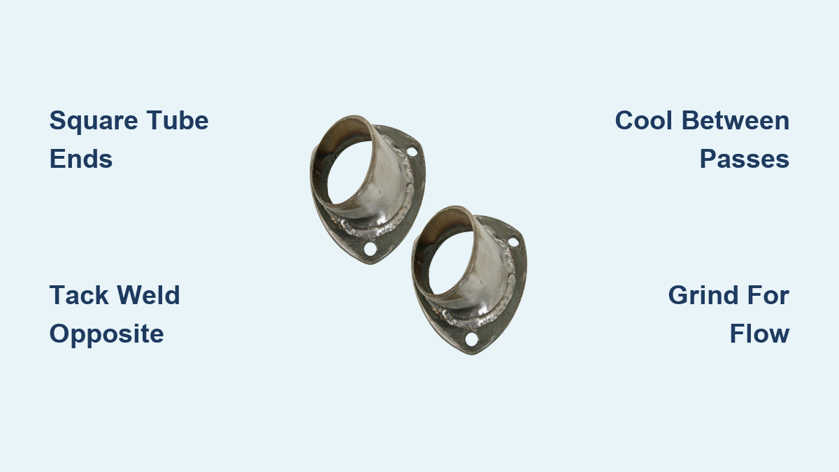
Begin by ensuring all primary tubes are cut perfectly square and flat at their ends using a dedicated tube-cutting jig, which dramatically improves accuracy compared to freehand cutting. Verify tube squareness with a precision square before proceeding, and grind any high spots or burrs that would prevent flush contact between tubes. The merge area where all four tubes converge requires absolute precision to create tight joints that minimize filler material requirements.
Position the tubes in your alignment jig, verifying all four are flat and coplanar before any welding occurs. Place tack welds in the center of the primaries where they’ll be covered by the collector – this allows easier removal of the alignment jig later. Remember that light tacks are sufficient at this stage; the actual structural strength comes from the final welds. After tacking, remove the jig and verify once more that the primaries remain flat and square using a flat table surface.
How to Verify Tube Alignment Without Specialized Jigs
If professional alignment jigs aren’t available, create a simple verification system using a flat table surface and precision square:
- Position the header assembly on a clean, flat work surface
- Place a precision square against two adjacent primary tubes
- Check that all four tubes contact the square simultaneously
- If gaps exist, use gentle persuasion with a rubber mallet to adjust alignment
- Re-tack weld after achieving proper alignment before proceeding
Installing Merge Bullets Without Distortion or Misalignment
The merge bullet (also called a merge spike or star piece) fills the central gap where primary tubes converge, and its assembly requires careful technique to prevent distortion during welding.
Begin by standing the bullet pieces together as they’ll be positioned in the collector. Slip a round assembly tool with matching notches over the top of the bullet assembly, ensuring the notches align with the sides of the merge bullet. This tool is essential for holding bullet pieces in correct relative position during welding, preventing the warping that commonly occurs when attempting freehand assembly.
Tack-weld the bullets together while the assembly tool remains in place, working on opposite sides to compensate for material shrinkage as the metal cools. Uneven cooling causes distortion that moves pieces out of alignment, but tacking opposite sides first allows each weld to pull the assembly toward center rather than twisting it out of shape. After tacking, remove the tool and complete finish welds using the same alternating pattern.
Step-by-Step Welding Technique for Leak-Proof Collector Joints
The actual welding process requires specific techniques that prevent warping while creating strong, leak-free joints that withstand extreme operating conditions.
When installing a slip-on merge collector, focus on creating strong joints at critical points rather than attempting full circumferential welding. The professional technique involves: welding approximately 25 degrees on each primary at a time, then moving to another pipe before returning to the collector. This cycling prevents excessive heat buildup in any single area and dramatically reduces warping risk.
For the central star area where tubes converge, weld through the outlet of the collector rather than attempting to access the inlet side from underneath. This approach provides better visibility and access while allowing more complete weld penetration where it matters most. Always weld the star piece to the header tubes and to each adjoining tube section before attaching the collector, then weld the collector over the outside for additional strength.
Make welds on opposite sides of the assembly to compensate for material shrinkage throughout the welding process. As one area cools and contracts, the opposite weld counteracts the distortion that would otherwise pull the assembly out of alignment. This technique becomes increasingly important as the assembly grows larger.
Avoiding Warping During Header Collector Welding Process
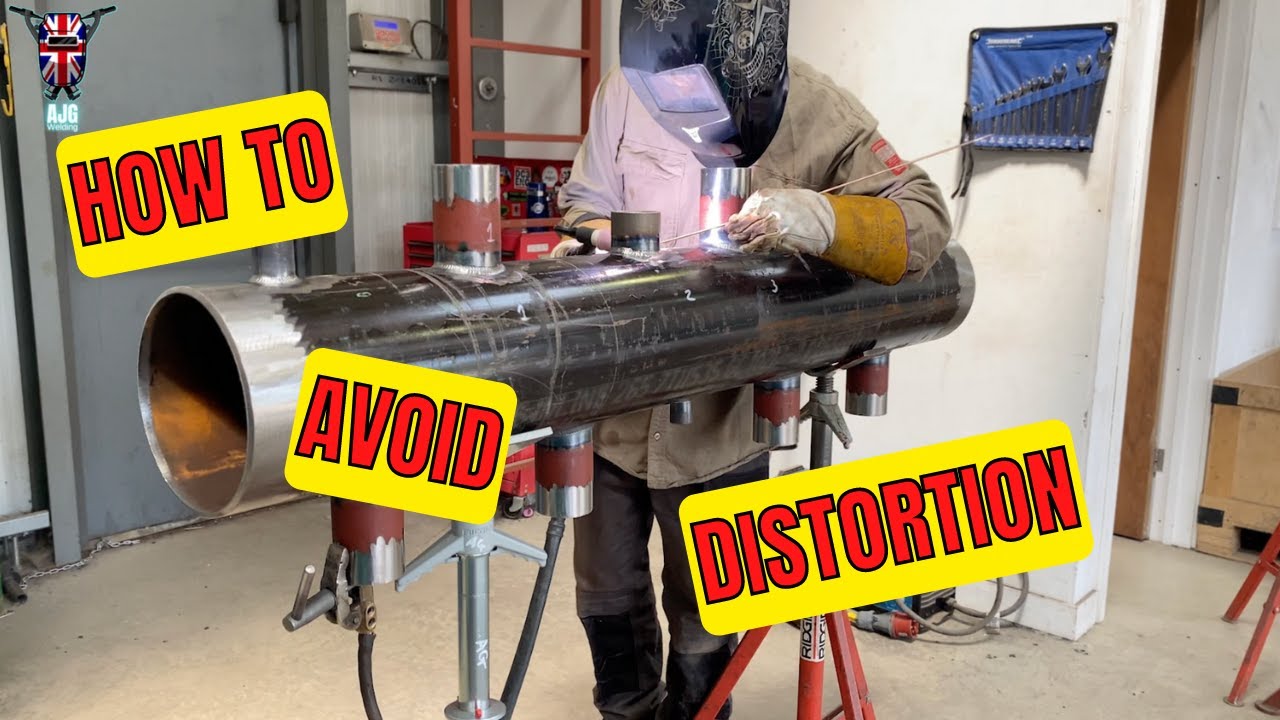
Header warping remains the most common failure during collector welding, but proper heat management techniques prevent this frustrating problem.
Never weld continuously around any single tube – this concentrates heat and causes uneven expansion that results in warping when the assembly cools. Instead, work in short segments of approximately 25 degrees of arc, then move to a different location, allowing the previous weld to cool before returning. This distributes heat evenly across the assembly.
Allow the header to cool completely between major welding stages rather than rushing to completion. Headers built in multiple sessions with full cooling between sessions consistently demonstrate fewer stress-related problems than those completed in marathon welding sessions where accumulated heat never fully dissipates.
For stainless steel collectors, particularly turbo applications using 321 stainless, bracing becomes essential due to the extreme heat and vibration cycles involved. Proper bracing at stress points like the collector and flange areas prevents fatigue failures during use.
Critical Post-Weld Cleanup for Optimal Exhaust Flow
After welding is complete, professional-level cleanup transforms a functional but rough assembly into a high-performance header that flows as good as it looks.
Begin by grinding and blending welds into surrounding surfaces for optimal airflow, paying special attention to the merge area inside the collector where rough surfaces create turbulence that disrupts exhaust flow at precisely the point where smooth flow matters most. The difference between welded merge bullets before and after cleanup can be significant for flow characteristics.
Some builds include a transition cone after the collector to increase exhaust gas velocity, and a 3-bolt flange can be added for mounting. Remember that the reduction from collector outlet to the rest of the exhaust should be gradual rather than abrupt – transitions of 40 inches or more under the cab allow exhaust flow to adjust smoothly before any diameter changes.
Common Collector Welding Mistakes That Cause Exhaust Leaks
Understanding these frequent errors helps you avoid costly rework and ensures your header collector performs as intended:
- Insufficient tube preparation – Skipping the squareness verification step guarantees misalignment that becomes impossible to correct after welding begins
- Rushing the cooling process – Attempting to complete all welding in one session without allowing proper cooling between passes creates residual stress that leads to cracks
- Improper heat distribution – Focusing too much heat in one area causes localized warping that compromises the entire assembly
- Inadequate merge bullet installation – Poorly aligned merge bullets create turbulence that reduces performance regardless of weld quality
Before final installation, inspect all welds for cracks, porosity, and incomplete penetration. A visual inspection supplemented by light tapping with a screwdriver handle can reveal hidden problems that would otherwise manifest as exhaust leaks during use. Address any issues immediately rather than hoping they’ll resolve themselves during operation.
Mastering header collector welding requires practice, but applying these professional techniques from your first project dramatically improves results. Start with simpler slip-on collector designs to build confidence before progressing to fully welded merge collectors, and each project will develop your skills for increasingly complex fabrication challenges. With proper technique, your header collectors will deliver leak-free performance for the life of your exhaust system.
Leave a Reply