When you weld pressure vessels, a single defect can trigger catastrophic failure with devastating consequences. These specialized containers hold significant potential energy under high pressure, making weld quality non-negotiable for safety and regulatory compliance. Industries from chemical processing to pharmaceutical manufacturing depend on properly welded pressure vessels that maintain structural integrity throughout their service life. This guide delivers the essential techniques, material considerations, and safety protocols you need to produce code-compliant pressure vessel welds that perform reliably in demanding applications.
Critical Pressure Vessel Design Elements Affecting Weld Integrity
Pressure vessels must withstand extreme internal forces without failure, requiring specific design approaches that directly impact your welding strategy. The cylindrical or spherical geometry isn’t just aesthetic—it distributes stress evenly without corners that create dangerous concentration points. Understanding these design fundamentals helps you recognize why certain welding techniques and procedures are mandatory for safe pressure vessel construction.
Why Cylindrical and Spherical Shapes Dominate Pressure Vessel Design
You’ll rarely encounter rectangular pressure vessels because sharp corners create stress concentration points that dramatically increase failure risk. Cylindrical vessels distribute hoop stress evenly around their circumference, while spherical designs provide the most efficient stress distribution of all geometries. When welding cylindrical vessels, ensure your joint preparation accommodates the constant radius to maintain uniform stress distribution. Any irregularities in your weld bead profile become potential weak points where pressure can concentrate, so maintain consistent penetration and bead placement throughout the circumference.
Calculating Proper Wall Thickness for 150-200 PSI Applications
For stainless steel vessels operating at 175 PSI, the minimum wall thickness calculates to approximately 0.020 inches with 100% joint efficiency. However, when applying the more conservative ASME Code joint efficiency factor of 0.65 (used when X-ray inspection isn’t performed), the required thickness increases to 0.031 inches. This explains why schedule 10 stainless steel pipe (0.120-inch wall thickness) provides a substantial safety margin for 150 PSI applications—offering more than six times the minimum required thickness. Always verify your calculations against ASME Section VIII requirements before beginning fabrication, as inadequate wall thickness represents one of the most common causes of pressure vessel failure.
Essential Material Selection for Code-Compliant Pressure Vessel Welding

The base material you select directly determines your welding procedure parameters, filler metal choice, and required preheat temperatures. Carbon steel remains the most common choice for general industrial applications due to its favorable strength-to-cost ratio and established welding procedures. However, stainless steel grades 304 and 316 become essential when corrosion resistance matters for pharmaceutical, food processing, or chemical applications where contamination control is critical.
Carbon Steel vs. Stainless Steel: Choosing the Right Base Material
When welding carbon steel pressure vessels, pay special attention to hydrogen control to prevent cold cracking in the heat-affected zone. For vessels operating below 400°F, ASTM A516 Grade 70 provides excellent weldability and strength at moderate cost. For stainless steel applications, particularly in sanitary environments, use low-carbon “L” grades (304L or 316L) to prevent carbide precipitation during welding that would compromise corrosion resistance. Never substitute materials without requalifying your welding procedure, as material changes affect critical parameters like heat input and cooling rates that determine weld integrity.
Preventing Cross-Contamination When Welding Stainless Steel
Cross-contamination between carbon steel and stainless steel tools creates “after-rust”—light rust-colored discoloration appearing hours after welding due to steel particles transferred to stainless surfaces. To prevent this:
- Maintain separate dedicated grinding and brushing tools for stainless applications
- Store stainless steel brushes in sealed containers when not in use
- Never use the same wire brush on carbon and stainless steel without thorough cleaning
- Visually inspect surfaces for embedded contaminants before welding
Surface Preparation Techniques That Prevent Common Weld Defects
Proper surface preparation represents your most cost-effective investment in pressure vessel weld quality. Inadequate preparation introduces defects requiring expensive rework and potentially causing field failures. The relationship between preparation quality and final weld integrity is direct—surface contaminants become weld defects that compromise pressure containment capability.
Eliminating Nitride Contamination from Plasma-Cut Edges
Plasma cutting with compressed air creates nitrides that extend 0.005-0.010 inches below the surface, causing brittleness and porosity in your welds. Removing nitrides requires aggressive techniques:
- Use flap discs or flap wheels that remove a small amount of base material
- Avoid bonded abrasive wheels that quickly load with nitride compounds
- Verify complete removal by checking for uniform surface appearance
- Perform final cleaning with appropriate wire brushes matched to your base material
Proper Wire Brushing Methods for Multi-Pass Welding Applications
The most effective cleaning approach involves wire brushing immediately after each pass while the weld surface remains warm. This prevents slag hardening and makes removal significantly easier. Use only the weight of the tool itself—pushing down hard indicates your brush is inappropriate for the application. For aluminum vessels, ensure complete removal of hydrocarbon contamination as even trace amounts introduce hydrogen that forms porosity during solidification.
Optimal Welding Processes for Pressure Vessel Fabrication
Several welding processes deliver acceptable results for pressure vessel construction, but each has specific applications where it excels. Selecting the right process for your material, thickness, and quality requirements significantly impacts your success in producing code-compliant welds.
When to Use TIG Root Passes with Stick Welding Fill Passes
For critical pressure vessels, combine TIG root passes with SMAW fill passes to achieve maximum integrity. The TIG process provides superior root penetration and cleanliness where the weld contacts vessel contents, while stick welding delivers efficient fill pass deposition. Ensure complete slag removal between passes and maintain proper interpass temperature (typically 300-400°F for carbon steel) to prevent hydrogen entrapment. Never skip the TIG root pass on vessels requiring x-ray quality, as this single step prevents most root-side defects that cause pressure leaks.
Gas Mixtures for Stainless Steel Pressure Vessel Welding
Stainless steel welding requires precise shielding gas formulations to prevent oxidation and ensure proper bead profile. Use these gas mixtures for optimal results:
- Carbon steel: 75% argon/25% CO₂ for general applications; add 1-2% oxygen for improved wetting
- 304/316 stainless: Tri-mix (90% helium/7.5% argon/2.5% CO₂) for spray transfer; 98% argon/2% CO₂ for short circuit
- Duplex stainless: Specialized mixtures with nitrogen additions to maintain phase balance
Critical Safety Testing: Hydrostatic vs. Pneumatic Pressure Testing
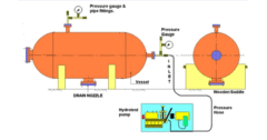
Testing your completed pressure vessel properly verifies integrity before service and represents your final quality checkpoint. Hydrostatic testing with water remains the gold standard due to its inherent safety advantages over pneumatic testing with compressed air.
Why Water Testing Is 160x Safer Than Air for 200 PSI Vessels
A vessel failing during 200 PSI pneumatic testing releases approximately 160 times more energy than the same volume of water at identical pressure. Water’s incompressibility means vessel failure results in a relatively benign liquid release rather than explosive expansion. Always test to 1.5 times design pressure per ASME requirements, but never use pneumatic testing unless hydrostatic is genuinely impractical—the safety margin simply isn’t worth the risk.
Proper Hydrostatic Test Procedures to Avoid False Failures
Complete filling with minimal air entrapment proves critical for accurate hydrostatic testing. Air pockets compress during pressurization, creating unpredictable pressure responses that mimic leaks. Maintain test pressure for at least 30 minutes while inspecting all welds for leakage. For small vessels under 5 gallons, hand-operated grease guns provide precise pressure control with minimal risk if failure occurs.
Common Pressure Vessel Weld Failures and How to Prevent Them
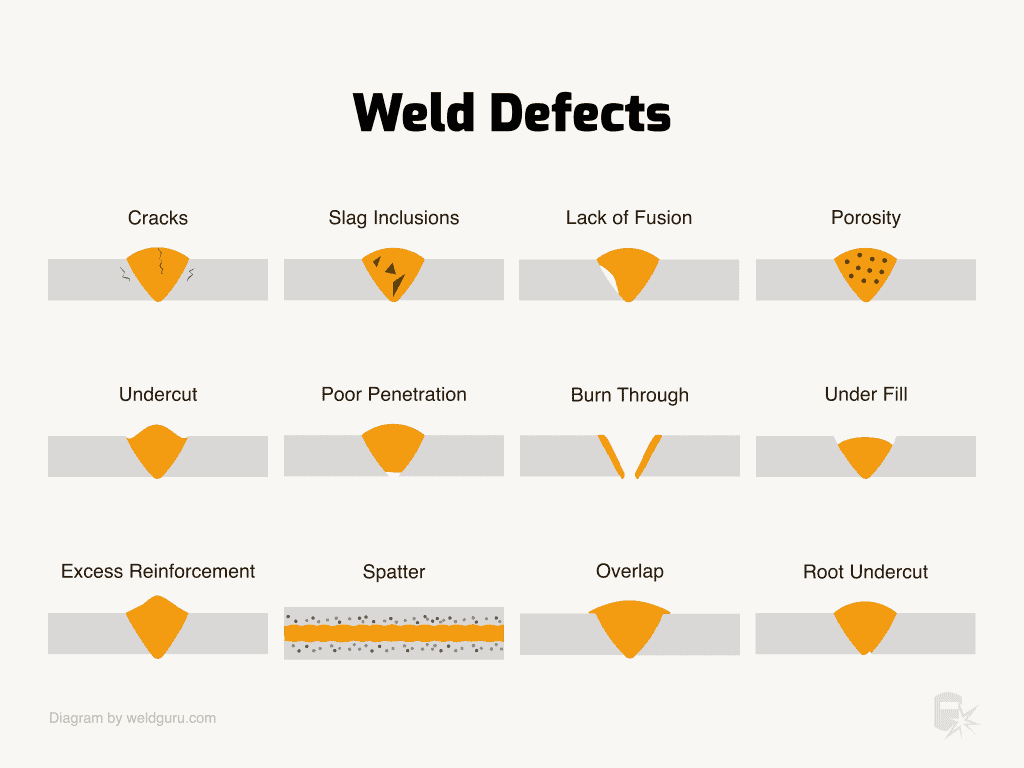
Understanding defect mechanisms helps you prevent issues before they occur rather than correcting them after failed inspections. Pinhole leaks, lack of fusion, and cracking represent the most common failure modes in pressure vessel welding.
Fixing Pinhole Leaks in MIG-Welded Pressure Vessels
Pinhole leaks typically indicate porosity rather than inadequate joint preparation. Address this by:
- Using a hot start function if your welder has this feature
- Welding past the original start point before overlapping to fill the crater
- Ensuring proper shielding gas coverage (20-25 CFH for carbon steel)
- Maintaining correct gun angle (10-15 degrees travel angle)
Preventing Hot Cracking in Thick-Section Welds
Hot cracking occurs when low-melting-point constituents segregate to grain boundaries during solidification. Prevent it by:
- Matching filler metal composition to base material
- Controlling heat input to minimize temperature gradients
- Maintaining proper interpass temperature
- Using proper bead placement to avoid centerline segregation
ASME Code Compliance Requirements for Legally Certified Vessels
Compliance with ASME Boiler and Pressure Vessel Code Section VIII represents the legal standard for commercial pressure vessels in most jurisdictions. Understanding these requirements prevents costly rework and certification delays.
Documenting Welding Procedure Qualifications (PQRs)
Your welding procedure must undergo documented qualification testing before production begins. This requires welding test coupons that undergo mechanical testing (tensile, bend, hardness) and non-destructive examination. Successful qualification establishes your Procedure Qualification Record (PQR), which documents approved parameters for production welding. Never deviate from qualified parameters without requalification, as even minor changes can invalidate your certification.
Essential Non-Destructive Testing Methods for Code Compliance
X-ray inspection provides the most comprehensive evaluation of weld integrity for critical pressure vessels, detecting subsurface cracks, porosity, and inclusions. Ultrasonic testing offers advantages for detecting planar defects like cracks that might not appear in radiography. Always coordinate your inspection plan with your Authorized Inspector early in the process to ensure compliance with code requirements.
Key Takeaways for Successful Pressure Vessel Welding
Welding pressure vessels demands exceptional attention to detail at every stage from material selection through final testing. Prioritize proper surface preparation, use appropriate welding processes for your application, and implement rigorous quality control throughout fabrication. Always test to ASME requirements using hydrostatic methods whenever possible, and maintain complete documentation of all procedures and inspections. By following these protocols consistently, you’ll produce pressure vessels that perform safely and reliably throughout their service life while meeting all regulatory requirements.
Leave a Reply