Wiring a welder plug correctly isn’t just about making connections—it’s about creating a safe, reliable power source that prevents electrical fires and protects your expensive welding equipment. Every year, improper electrical installations cause thousands of preventable workshop accidents, from melted outlets to catastrophic equipment failure. When your welder suddenly shuts down mid-project or your circuit breaker trips during critical welds, the problem often traces back to incorrectly wired plugs. This guide gives you the precise steps to wire your welder plug safely and correctly the first time, ensuring optimal performance while meeting electrical code requirements.
Before you touch a single wire, understand that mistakes in welder plug wiring carry serious consequences. Using undersized wire creates dangerous overheating conditions, while reversed hot and neutral connections can damage your welder’s internal components beyond repair. If you’re uncomfortable with any step in this process, stop immediately and consult a licensed electrician—your safety is worth far more than any potential time savings. Now let’s get your welding station powered up properly.
Match Your Welder’s Voltage and Amperage Requirements
Selecting the correct plug type prevents immediate equipment damage and ensures your welder operates at peak performance. Most professional-grade MIG and TIG welders require 240-volt power, while smaller flux-core models may run on standard 120-volt circuits. Your welder’s nameplate—typically located near the power input—specifies exact voltage and amperage requirements that dictate your wiring approach.
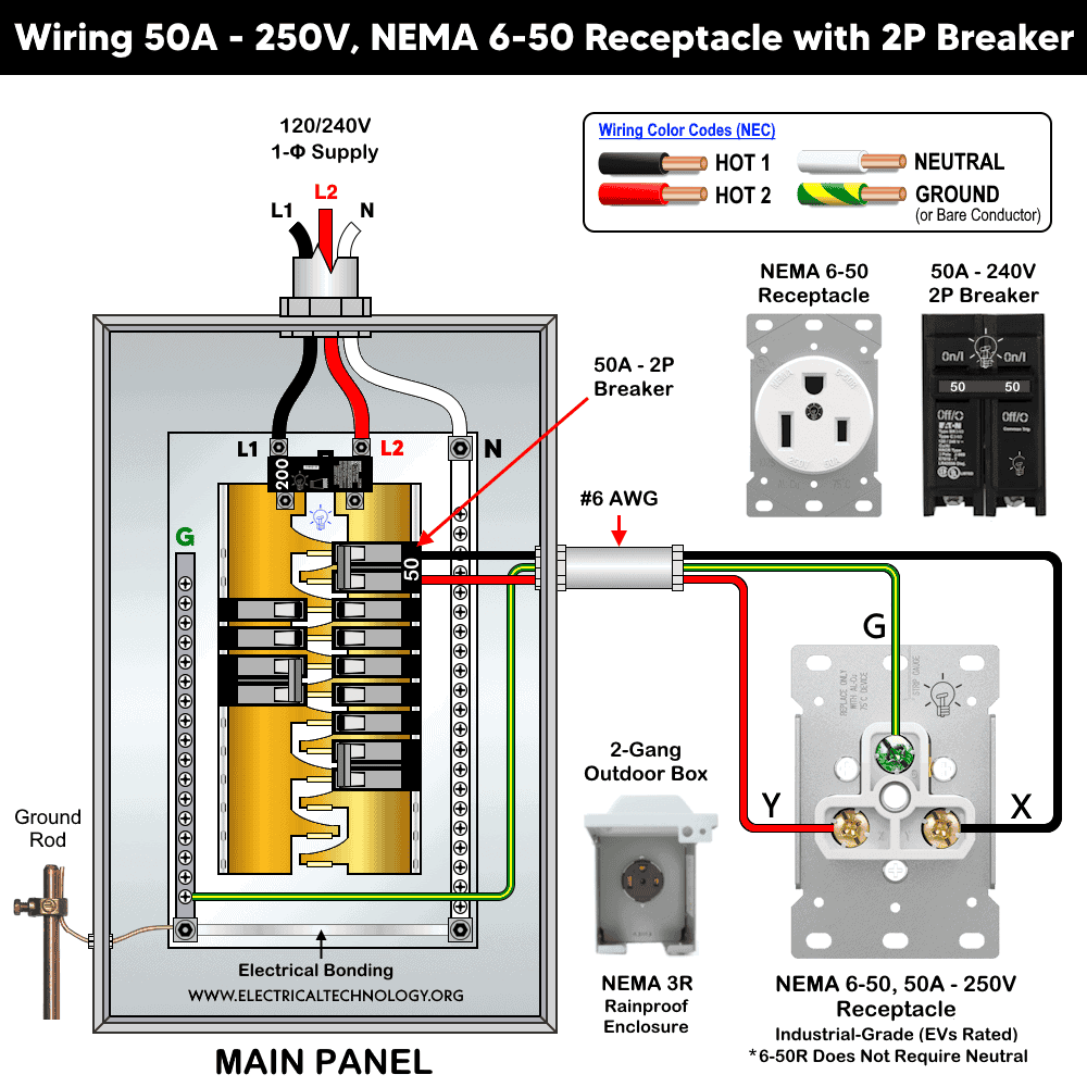
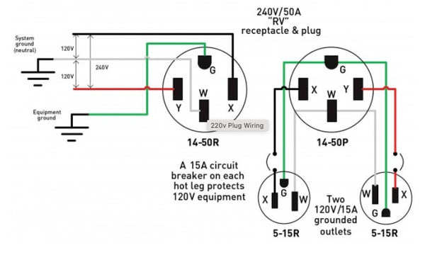
The NEMA 6-50 plug serves as the industry standard for 240-volt welding equipment in residential and commercial workshops. This four-prong configuration includes two hot wires (each carrying 120 volts), a neutral wire, and a dedicated ground wire, supporting equipment drawing up to 50 amps continuously. Never substitute a NEMA 10-50 three-prong plug for new installations—these older designs combine neutral and ground connections internally, creating serious shock hazards and violating modern electrical codes. Industrial three-phase systems typically use CS6375 plugs, but these are rare in home workshops.
Why Four-Prong Beats Three-Prong for Safety
Understanding the critical difference between three-prong and four-prong configurations prevents dangerous code violations. Modern electrical standards require separate grounding and neutral paths—a safety feature four-prong plugs provide but three-prong versions lack. In three-prong systems, the neutral and ground connect at the receptacle, creating a potential shock hazard if the neutral wire becomes disconnected during operation. If your welder came with a three-prong plug but your workshop uses modern four-prong outlets, replace the plug rather than using dangerous adapters that bypass essential safety features.
Gather Exact Materials Before Starting
Assembling all necessary components before beginning prevents mid-installation delays and ensures continuous, safe progress. Your specific requirements depend on your welder’s amperage rating, but certain elements remain consistent across most installations.
Select Correct Wire Gauge for Your Amperage
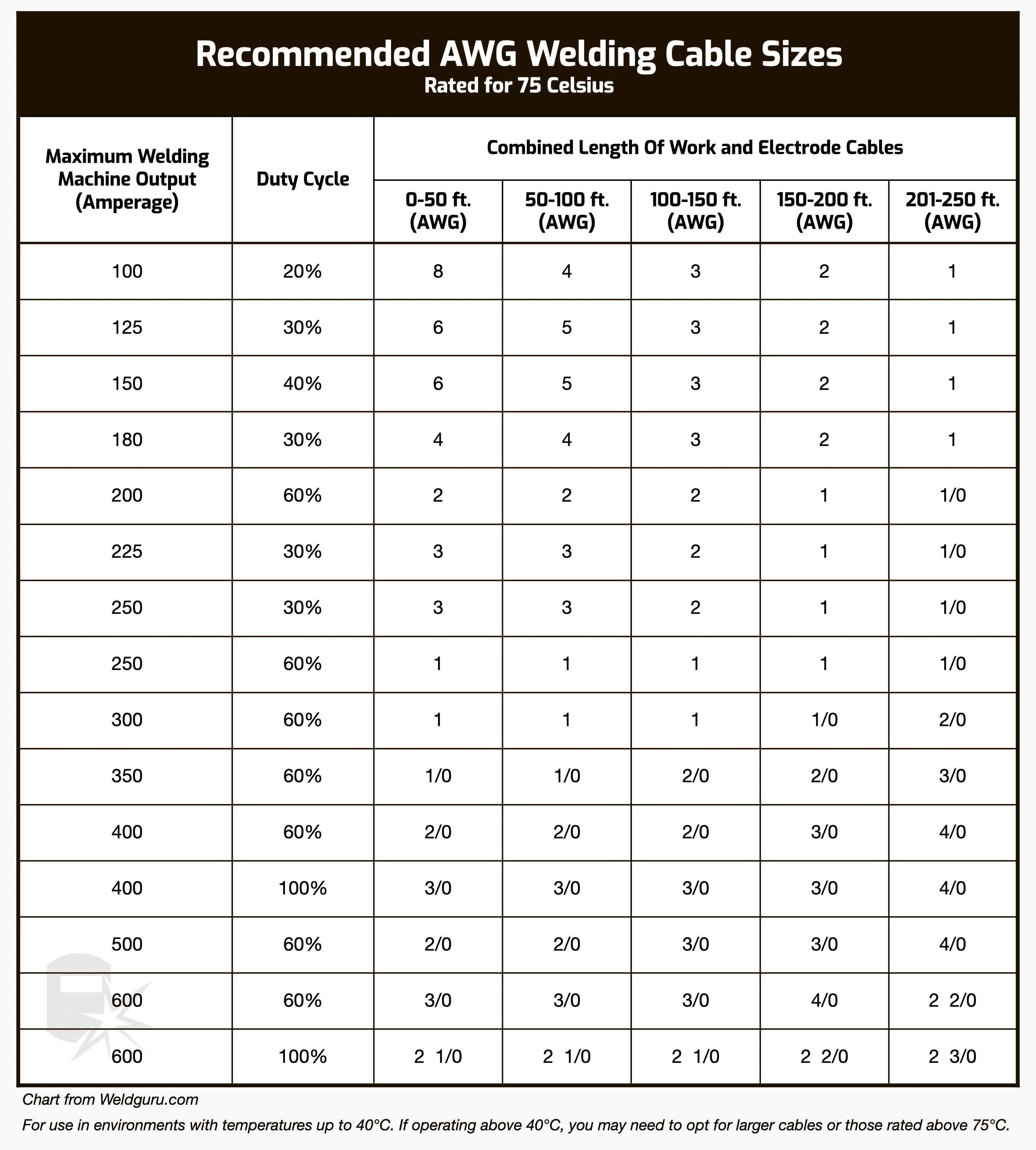
Wire gauge selection follows a strict relationship with amperage requirements. For 30-amp circuits, 10 AWG copper wire provides adequate capacity without overheating. Fifty-amp circuits demand 8 AWG copper minimum, while 60-amp installations require 6 AWG copper wire. Never use undersized wire—this creates dangerous resistance that generates excessive heat during welding operations, potentially melting insulation and starting fires. Aluminum wiring requires larger gauges and special connectors due to its higher resistance, making copper the preferred choice for workshop installations.
Choose Proper Circuit Breaker Size
Your circuit breaker must precisely match both wire gauge and welder requirements. A 50-amp welder needs a dedicated 50-amp double-pole breaker protecting 8 AWG copper wire—no exceptions. Undersized breakers trip constantly during welding, disrupting your work, while oversized breakers fail to protect against dangerous overload conditions. The breaker mounts in your electrical panel and provides essential overcurrent protection that shuts power off before wires overheat.
Create a Dedicated Welder Circuit
Welders demand their own dedicated circuit—never share power with other workshop equipment. Welding machines draw substantial current during operation, and shared circuits cause voltage drops that damage both your welder and other tools connected to the same line.
Calculate True Circuit Requirements
Your welder’s nameplate specifies input amperage at maximum output, which determines your circuit requirements. A machine rated at 50 amps input requires a full 50-amp circuit even if you typically weld at lower settings—the circuit must handle maximum potential draw, not typical usage. Add 20-30% safety margin when selecting wire gauge and breaker size, always rounding up to standard sizes rather than cutting margins close.
Install Proper Wiring Through Your Workshop
Running cable through finished walls requires careful planning—either fish wires through existing cavities or cut access holes with plans to patch afterward. For indoor dry locations, NM-B (non-metallic sheathed) cable works well, while UF (underground feeder) cable or conduit-protected wiring handles damp areas and outdoor runs. Secure the cable with staples every four feet and within twelve inches of each electrical box, avoiding sharp edges that could damage insulation over time.
Wire the Receptacle Correctly for Safety
With the circuit prepared and power confirmed OFF at the panel, installing the receptacle requires precise attention to terminal identification and connection security. Each screw terminal accepts specific conductors, and miswiring creates immediate safety hazards.
Mount the Receptacle Box Properly
Old-work boxes with integrated clamps work well for existing walls, while new-work boxes mount directly against studs for fresh installations. The box must sit flush with your wall surface and remain secure without wobble. In garage or workshop environments, weatherproof boxes with in-use covers provide essential protection against dust and moisture that could compromise electrical connections.
Make Secure Terminal Connections
Strip exactly the right amount of insulation—typically enough to reach the terminal without exposed conductor visible outside. Loop the wire clockwise around each terminal so tightening the screw pulls the loop closed rather than opening it. Tighten each screw to the torque specification listed on the receptacle documentation (typically 20-45 inch-pounds), using a torque screwdriver for accuracy. Loose connections overheat during use, melting plastic components and eventually starting fires.
Connect the Welder Plug to Power Cord
After completing the receptacle installation, wiring the plug on your welder’s power cord follows similar principles but requires working with the machine’s cord cap rather than a stationary outlet.
Thread Cord Through Strain Relief First
Before making any connections, thread the power cord through the cord cap’s strain relief mechanism—this critical step prevents frustrating reassembly issues. The strain relief clamps around the outer jacket of the power cord, securing it against pulling forces that would otherwise stress internal connections. Without proper strain relief, repeated cord movement eventually breaks wire strands at terminals, creating dangerous intermittent connections.
Match Wires to Correct Terminals
Connect conductors following standard color conventions: black and red to hot terminals (usually marked X and Y), white to neutral (if present), and bare or green to ground. Some cords use colored screw terminals instead of markings—verify terminal functions before tightening connections. Secure each connection with appropriate torque, then close the cord cap and tighten all screws completely before testing.
Test Installation Before First Weld
Electrical testing before first use catches mistakes that could damage equipment or cause injury. Skipping these tests because everything “looks right” invites hidden dangers that manifest during actual welding.
Perform Critical Continuity Checks
Set your multimeter to resistance mode and verify correct connections before applying power. Test between ground and each hot terminal—you should see near-zero resistance indicating solid connections. Test between hot terminals for expected voltage path resistance. Any open circuits or unexpected resistances indicate wiring errors requiring correction before proceeding.
Verify Voltage at Receptacle
With the circuit breaker on, insert multimeter probes into each slot of the receptacle. Hot-to-hot should read approximately 240 volts, while each hot-to-ground reads approximately 120 volts. Record all readings and compare against expected values—significant deviations indicate wiring errors or supply problems that must be corrected before connecting your welder.
Follow Essential Safety Practices During Installation
Electrical work demands respect for the hazards involved, especially with high-current welder installations in potentially conductive workshop environments.
Implement Lockout/Tagout Procedures
Treat every wire as potentially live until testing confirms otherwise. Use lockout/tagout procedures to prevent accidental power restoration while working—install a personal lock on the breaker panel that only you can remove. Wear insulated gloves and safety glasses throughout the installation process, and never work alone when dealing with high-voltage circuits.
Understand Local Electrical Code Requirements
The National Electrical Code (NEC) articles 250 and 630 provide foundational requirements, but local amendments often add specific restrictions. Many jurisdictions require permits and inspections for new 240-volt circuit installations, and working without permits creates legal liabilities if fires or injuries occur. Contact your local building department before starting to understand requirements in your area.
Key Takeaways: Proper welder plug wiring requires matching plug types to your machine’s specifications, using correctly sized wire and breakers, making torqued connections, and thorough testing before use. Always follow local electrical codes and prioritize safety—when uncertain, hire a licensed electrician. Regularly inspect your installation for signs of wear, as loose connections and damaged components become increasingly dangerous over time. A correctly wired welder plug provides decades of reliable service, while improper installations create ongoing safety hazards that threaten both your equipment and your workshop.
Leave a Reply