
Welding angle iron corners consistently challenges even experienced fabricators. The core difficulty isn’t making a weld hold—it’s creating joints that remain square and strong despite intense heat causing metal to warp and twist. Whether you’re building shelves, tables, or structural frames, mastering how to weld angles separates amateur attempts from professional results. This guide delivers the specific techniques you need to produce accurate, durable angle joints every time.
The fundamental decision when starting any angle welding project involves selecting the right joint configuration for your application. Structural applications demand full-penetration welds capable of handling expected loads, while cosmetic projects may permit lighter welds that get ground smooth. Understanding whether to miter, cope, or overlap your angle iron before striking that first arc prevents costly mistakes and ensures optimal results for your specific project.
Miter Cutting for Perfect Angle Iron Corners

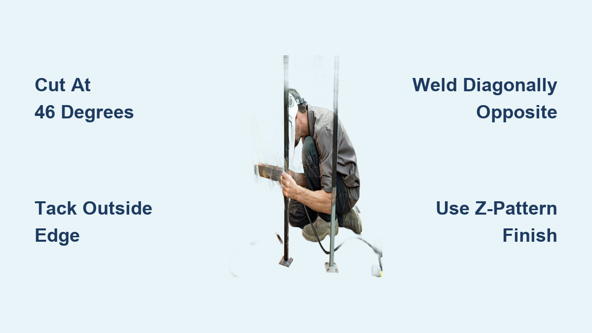
Mitering remains the most common technique for creating clean-appearing corners on angle iron projects, but proper execution requires specific knowledge most beginners miss. The critical detail that transforms mediocre miters into professional joints involves cutting at 46 degrees rather than the expected 45 degrees.
Why 46 Degrees Creates Better Mitered Joints
Cutting angle iron at 46 degrees rather than 45 creates a small intentional gap at the inside corner when assembling a 90-degree joint. Experienced fabricators call this “gap-o-sis” for good reason—it serves three critical functions: it allows pieces to swing freely during squaring without binding, provides a channel for weld penetration from the inside, and creates a reservoir for filler material. Without this gap, your tack welds will likely break when you try to adjust squareness.
Before cutting production pieces, lay your angle stock together and make test cuts to verify the gap size. Too small a gap prevents adjustment during assembly, while an excessive gap requires more filler material and increases distortion potential. The ideal gap allows visible light through when pieces are assembled but remains narrow enough that filler metal bridges easily.
Proper Miter Tack Welding Sequence
Place your first tack weld on the extreme outside of the upright leg at the very top of the corner. This placement strategy allows the joint to bend slightly without breaking the tack, enabling final adjustments. Continue tacking remaining pieces to form the complete frame, rechecking squareness frequently. After achieving proper alignment, place a tack on the inside of the miter where it can be ground flush if necessary before flipping the frame to weld the bottom of the miter.
Critical mistake to avoid: Placing tacks too deep in the “crotch” of the miter. Tacks positioned too far inside cannot be ground flush later, leaving visible imperfections in your finished corner.
Coping Technique for Maximum Joint Strength
Coping creates fundamentally stronger joints than mitering by dramatically increasing welding surface area. Rather than creating a continuous mitered seam, coping involves cutting a notch in one piece that matches the profile of the adjacent piece’s inner corner.
Executing Proper Coping Cuts
Begin coping by carefully measuring and marking the exact profile needed. Trace the inner corner of one angle piece onto the mating piece, then cut along your marked lines using a bandsaw, cutting torch, or angle grinder. The goal is removing material from one leg of the angle so the adjacent piece fits flush against the remaining material. Test fit repeatedly during cutting to avoid removing too much material, which weakens the joint.
For fabricators with access to ironworker equipment, coping becomes substantially faster than hand-cutting miters. The mechanical notcher removes a clean profile in seconds, producing consistently accurate joints when properly set up. Some shops cope only the vertical faces while leaving horizontal surfaces butted together, balancing fabrication time against maximum strength benefits.
Welding Coped Joints for Structural Integrity
The resulting joint requires three separate welds per corner rather than the single continuous weld of a mitered joint. Start by welding the bottom seam where the coped piece meets the base material. Next, weld the vertical seam along the coped edge. Finally, weld the outside corner to complete the joint. This sequence distributes heat evenly and minimizes distortion while creating a joint significantly stronger than a mitered alternative.
Strategic Tack Welding to Prevent Distortion

Your tack welding approach directly determines whether your frame remains square or twists into an unusable configuration. Many beginners make the critical error of tacking all pieces rigidly before verifying alignment, locking in distortion before the first actual weld begins.
Optimal Tack Placement for Adjustability
Place initial tacks only on the extreme outside edge of the joint—never deep in the corner. Tacks positioned this way allow slight bending for final adjustments without breaking. After achieving proper squareness through diagonal measurement, add additional tacks only where necessary to maintain alignment. Remember: more tacks don’t mean better alignment—they mean less ability to correct errors.
For larger frames exceeding your work surface dimensions, use adjustable turnbuckles across corners. Weld pieces of round bar to each end of a turnbuckle, then tack the assembly across joined pieces. By adjusting the turnbuckle, you can fine-tune alignment after tacking but before final welding—a technique that professional fabricators rely on for precision work.
Diagonal Welding Sequence to Neutralize Distortion
The sequence in which you complete welds dramatically affects distortion. Welding all miter seams from outside to inside causes all angles to become less than 90 degrees as sides bend inward due to shrinkage—a common frustration for beginners.
Implementing the Balanced Welding Approach
After completing your first fillet weld, immediately move to the diagonally opposite fillet and weld that next. This balanced approach allows the two welds to pull against each other, neutralizing their individual distortion effects. Complete the remaining two fillet welds, then verify that butt joints remain flat before proceeding. Only after all four fillets are complete and the frame has become rigid should you weld the outside corners.
Key insight: Welding shrinks material most where welding stops. By welding diagonally opposite corners, you ensure shrinkage forces work in opposing directions simultaneously. When one weld pulls the frame in one direction, the opposing weld pulls it back—resulting in a frame that remains square.
Z-Pattern Technique for Flush Outside Corners
Achieving professional-looking outside corners requires specific technique rather than just grinding afterward. The Z-pattern approach produces welds that sit nearly flush with the base material, minimizing cleanup work while maximizing strength.
Executing the Outside Corner Weld
For outside corners, slow your wire feed slightly and use a Z-pattern motion as you make the pass. The slower feed rate reduces filler material buildup by allowing more melting of the base metal corner. As you move forward, oscillate the torch side to side in a slight zigzag pattern—this spreads the weld pool across the joint width while maintaining consistent penetration.
The goal is creating a weld that demonstrates good fusion with the base metal while building up minimally. When done correctly, the weld sits nearly flush with the surrounding surface, requiring only light grinding with a flap disc to achieve a smooth, professional finish. This technique works particularly well with 1/8-inch angle iron commonly used in workshop projects.
Hammering and Clamping to Correct Distortion
Despite best prevention efforts, some distortion typically occurs and requires correction. Knowing how to address these issues saves you from scrapping otherwise good work.
Effective Distortion Correction Methods
Hammer the welds after they’ve cooled but before grinding. The compressive force of hammer blows stretches the slightly compressed weld zone, counteracting some of the tensile shrinkage that caused distortion. This technique works best immediately after welding while the metal remains relatively soft.
For twisted frames, clamp the frame down to a solid surface with packers under the corners. Position packers to apply force in the correct direction, then gradually tighten your clamps. Decent G-clamps provide sufficient force for this purpose—smaller spring clamps typically lack the power to correct significant twist.
For diagonal correction issues, position the frame with the longer diagonal running vertically and gently bump that corner against a solid floor surface. This technique uses the frame’s own weight and impact force to move the corner, changing diagonal measurements without additional tools.
Adding Gussets for Reinforced Structural Joints
Basic corner construction provides adequate strength for many applications, but demanding loads require additional reinforcement. Understanding when and how to add gussets ensures your projects handle expected loads reliably.
Proper Gusset Installation for Maximum Strength
Cut triangular gussets from flat bar matching your angle iron thickness. Position each gusset so it extends well onto both legs of the angle iron—typically 2-3 inches on each side for 1/8-inch material. Tack the gusset in place, verify alignment, then complete the welds using the same diagonal sequence as your main frame.
For shelf applications, position gussets above the shelf surface to catch tension loads from items resting on the shelf. For compressor stands or other vibration-prone applications, install gussets on both sides of the corner for maximum rigidity. The added material dramatically increases joint strength while providing visual evidence of professional construction.
Finishing Welds for Professional Results
The final appearance of your welded project depends significantly on proper finishing techniques. Professional fabricators know that technique matters more than cleanup—proper execution minimizes the need for extensive grinding.
Achieving Clean, Professional Welds
Allow all welds to cool completely before beginning cleanup. Grinding too early can disturb hot weld metal and alter the weld profile. Start with a flap disc for initial material removal, then progress to finer grits for final blending. For most painted projects, finishing with 120-grit provides adequate smoothness.
For applications requiring nearly invisible welds, technique matters more than aggressive grinding. A properly executed outside corner weld using the slow feed Z-pattern technique can sit nearly flush with the base metal, requiring only minimal blending. The key is allowing enough base metal melting to fuse with the filler without building up excessive deposit—master this, and you’ll spend far less time grinding.
Welding angle iron corners consistently well requires understanding joint preparation, frame setup, welding technique, distortion control, and finishing. By applying these specific techniques systematically, you can produce strong, square, professional-quality welded angle frames for any application. The investment in mastering how to weld angles pays dividends in every project you build, reducing frustration and improving results with every weld you make.